
Summary
Artec Spider II scan to CAD is the current answer inside Artec’s range when the job is small, detailed, and close-range. Vendor-published specs put Spider II at up to 0.05 mm accuracy, up to 0.05 mm resolution, a 0.19–0.3 m working distance, a 128 × 104 mm to 171 × 152 mm field of view, and real-time fusion at up to 30 fps. [1] It is also the model that replaced Space Spider: Artec now labels Space Spider a legacy scanner and points buyers to Spider II as its successor, so a 2026 purchase decision is between Spider II, Eva, and a metrology-class workflow — not between Spider II and its own predecessor. [3]
- Choose Spider II if the part is small and detail-dense and you want the current close-range platform: up to 0.05 mm accuracy, up to 0.05 mm resolution, up to 30 fps, up to 8 mln points/s. [1]
- Choose Eva if the part is larger and you need a much bigger capture zone, even though its vendor-published fine-detail figures are looser at up to 0.1 mm accuracy and up to 0.2 mm resolution. [5]
- Keep using a Space Spider if you already own one — Artec Studio still supports it as a discontinued model — but treat it as a legacy device rather than a shortlist item. [3] [7]
- Choose a metrology-grade workflow if CAD acceptance depends on controlled uncertainty, documented inspection, and traceable validation rather than just a usable mesh. [10] [13]
What “scan-to-CAD” actually means
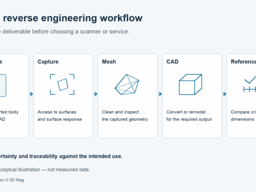
A scan-to-CAD workflow is not a button that turns a scan into a finished mechanical model. It is a conversion and remodeling process: capture the part, clean the data, align multiple scans, build usable geometry, and then recreate the design in CAD tools. For reverse engineering, the scanner gives you measured shape; the CAD system gives you editable intent. In practice, the result is usually a reference model, not an automatically recovered parametric part. [6] [9]
That distinction matters because file format does not equal editability. A point cloud is sampled points in space. A mesh connects those points into triangles. A watertight mesh is a closed triangle model that can help with downstream surfacing, but it is still not the same as a CAD solid with design features. NURBS surfaces are smooth mathematical patches often used to rebuild curves and freeform faces, while B-rep, short for boundary representation, describes a solid by its faces, edges, and vertices. STEP, IGES, or X_T files may carry surfaces or solids, but they do not guarantee a usable feature tree or original design intent.
- Point cloud — raw measured points from the scanner.
- Mesh — triangle surface built from the points.
- Watertight mesh — a closed mesh with no holes.
- B-rep/solid — a CAD solid defined by boundaries.
- NURBS surface — a mathematically smooth surface patch.
- Deviation map — color map showing scan-to-CAD differences.
- Registration/global registration — aligning multiple scans into one coordinate frame.
- Repeatability — how consistently the same setup produces the same result. [9] [18] [19] [20]
Artec Studio supports CAD objects, CAD primitives, import from external CAD applications, and export of CAD objects, which is why scan-to-CAD is best understood as a mixed measurement-and-reconstruction workflow rather than a single export step. [6]
Boundary context — where handheld structured-light scan-to-CAD fits
Handheld structured-light scanners fit into reverse-engineering workflows when you need fast capture of small to medium objects, practical portability, and enough geometric detail to rebuild CAD geometry from measured shape. NIST describes structured light scanners as portable short-range 3D imaging systems that use projected patterns, which is why they are commonly used for 3D scanner for CAD tasks rather than large-area surveying. [9]
Photogrammetry, LiDAR, and CT solve different problems: photogrammetry is image-based, LiDAR is better known for larger-scale distance capture, and CT can reveal internal features. They are relevant alternatives, but this article stays with handheld structured-light reverse engineering and the Artec Spider II scan to CAD workflow.
Spider II in 2026 — what it is, and what happened to Space Spider
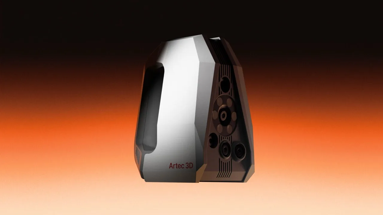
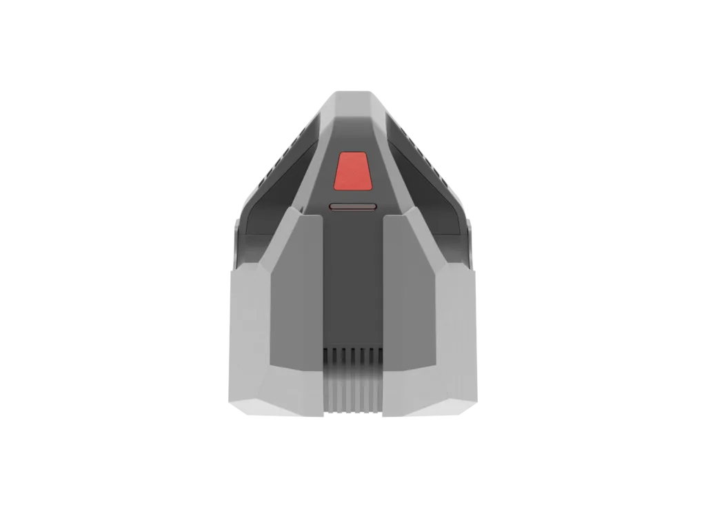
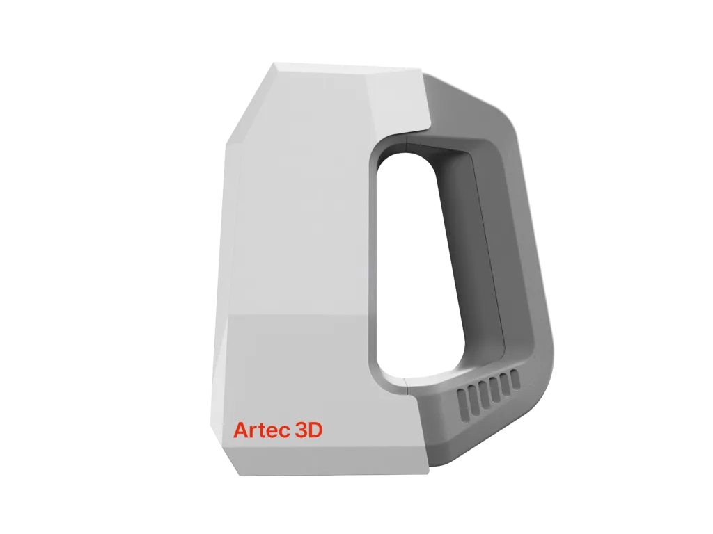
Artec Spider II is a handheld structured-light scanner for close-range reverse engineering and 3D scanner for CAD modeling on small, detailed parts. Artec specifies a 450 nm LED as the 3D structured-light source and a white LED array with CRI above 95 at 4000 K for texture, with a working distance of 0.19–0.3 m, a depth of field of 110 mm, and a field of view running from 128 × 104 mm at closest range to 171 × 152 mm at the far end. The volume capture zone is listed as 1,800 cm³. That geometry makes it a small-object tool: once the part gets larger, you still need more passes, more registrations, and more cleanup to cover the surface consistently. [1]
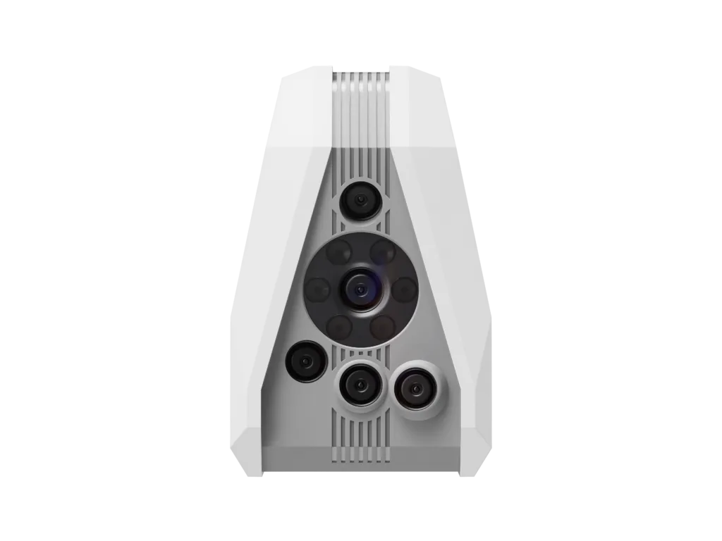
The important context for anyone researching this scanner is that it is not one option among two generations. Artec’s own legacy page states that Space Spider is a legacy scanner and directs readers to its successor, Artec Spider II, and Artec Studio’s specifications page lists Space Spider among discontinued models that remain compatible with the software rather than among current scanners. So the Space Spider is still a supported device in Artec Studio if you own one, but it is no longer part of the current line-up, and it should not appear on a 2026 shortlist as a new purchase. [3] [7]
Artec positions Spider II as a step up rather than a refresh, describing twice the resolution and four times the speed compared with Space Spider. The predecessor’s headline figures were up to 0.05 mm accuracy, up to 0.1 mm resolution, up to 7.5 fps and up to 1 mln points/s, with a 1.3 MP texture camera. Spider II keeps the accuracy class, halves the resolution figure to 0.05 mm, raises real-time fusion to 30 fps and acquisition to 8 mln points/s, and moves texture to a 5 MP sensor at 24 bpp. It also changes the host connection: Spider II is specified as compatible with Thunderbolt 4 hosts, where the older scanner ran over USB. [1] [2] [3]
Specs that matter for CAD modeling, without the accuracy traps
In metrology language, accuracy is closeness to the true value, precision is how tightly repeated measurements cluster, and repeatability is precision under repeatability conditions. A scanner can be very repeatable and still miss the true shape by a constant offset, so repeatability is not the same as accuracy. VIM provides those distinctions as measurement concepts, and they matter here because scan-to-CAD often mixes local sensor behavior with global reconstruction quality. [18] [19] [20]
That is why vendor local specs should not be converted directly into part tolerances. Spider II publishes an accuracy over distance figure of up to 0.05 mm + 0.3 mm/m, but that number is only one layer of the problem: after global registration, fusion, and CAD reconstruction, the whole-part deviation can be larger or smaller depending on how well the scans were aligned and cleaned. A scanner can be locally consistent on one patch yet drift across a larger stitched model. For example, two repeated scans of the same small boss can agree closely while the full housing still shifts after alignment. [1]
Resolution is also easy to overread. NIST notes that a theoretical lateral resolution does not by itself define the smallest distinguishable feature, and that deep, dark, shiny, and concave areas are harder for structured-light systems. So Spider II’s up to 0.05 mm resolution is best treated as an indicator of sampling density, not a promise that every rib, fillet, or slot will reconstruct cleanly. In practice, deviation analysis on the fused mesh and on the final CAD model tells you more than the raw point spec does. [9]
Accuracy over distance matters because scan span changes the error budget. A scanner with a short-range spec can still be useful for small parts, but once the part grows, each added pass increases the chance of registration error and cumulative drift. The 0.05 mm + 0.3 mm/m figure means the local number is only part of the story — and Artec’s product page carries a disclaimer reserving the right to update specifications, so all of these should be read as vendor-published up-to values. [1]
Artec Spider II scan-to-CAD workflow
The Artec Spider II scan to CAD workflow is practical only when you treat it as a sequence of decisions, not as a single capture-and-export action. Its close working distance, compact field of view, and up to 30 fps / up to 8 mln points/s capture rate shape how you plan coverage, overlap, and part handling. The higher frame rate mostly buys you a calmer scan session — you can move at a natural pace without dropping tracking — rather than a better model by itself. On the software side, Artec’s Max error and Quality value are internal per-frame parameters, not values in mm or %, and they become most meaningful after Global Registration and other preparation steps. [1] [8]
- Define CAD outcome and datums.
- Prep surface and environment.
- Capture strategy.
- Registration.
- Fusion.
- Mesh repair and simplification.
- CAD reconstruction path.
- Validation.
Each stage can degrade the downstream model if handled casually. Real-time fusion can be convenient, but an industry review notes the tradeoff between speed and accuracy and says Artec does not recommend it for metrology or serious measurement. That is why scan-to-CAD quality is usually decided long before surfacing begins: by datum planning, overlap, registration discipline, and how much deviation analysis you do on the fused mesh before you rebuild CAD geometry. [14]
Setup aids and the two scan-to-CAD paths
Preparation matters because target-free tracking is not the same as target-free success. With any Spider-class scanner, reflective surfaces, weak contrast, and neglected prep can make alignment harder, and NIST notes that deep, dark, shiny, and difficult concave features are common problem areas for structured-light scanners. Artec’s Max error / Quality value is useful here only as an internal alignment context, not as a simple pass-fail metric in mm. [8] [9]
- Spray — use removable anti-reflective spray when the part finish is too glossy for stable capture. [8]
- Temporary targets/markers — add them when tracking needs more stable alignment cues.
- Fixturing — hold the part so you can see more surfaces without losing registration.
- Add reference geometry — include known planes, cylinders, or other datums when the CAD intent depends on them.
- Exposure/lighting discipline — keep the scene stable enough that texture and tracking do not drift.
- Scanning angle strategy — vary angles to reduce occlusion and improve overlap between passes.
For a prismatic part, the goal is not to preserve every triangle but to recover the design logic. That usually means building around datums, then fitting or remodeling sections, cylinders, planes, and cones in CAD. This path is the usual choice when the end product needs editable, engineering-style features rather than a faithful surface copy. Artec Studio’s CAD tools support primitives, constraints, and patch-based operations that fit this style of reconstruction. [6]
For a freeform part, the target is often a clean surface network rather than a feature tree. In that case, you work from the mesh into autosurface or patch-based reconstruction, then refine the resulting NURBS surfaces until deviation is acceptable. The limitation is important: editable surfaces are not the same as original design intent, so a good-looking CAD body can still be a reverse-engineered approximation rather than the native model. [6]
A hybrid path is common in real projects: use prismatic feature reconstruction where the geometry is regular, then patch or surface the organic zones. That approach usually keeps the CAD model manageable while still honoring the measured shape.
“CAD export” in Artec Studio — what STEP, IGES, and X_T usually contain
Artec Studio documentation frames CAD support around CAD objects, CAD primitives, and freeform patch workflows, not around automatic, fully parametric feature-history reconstruction. In practice, that means the software can help you build CAD-ready geometry from scans, but the export is still the result of choices you make during remodeling, constraint fitting, and surface creation. [6]
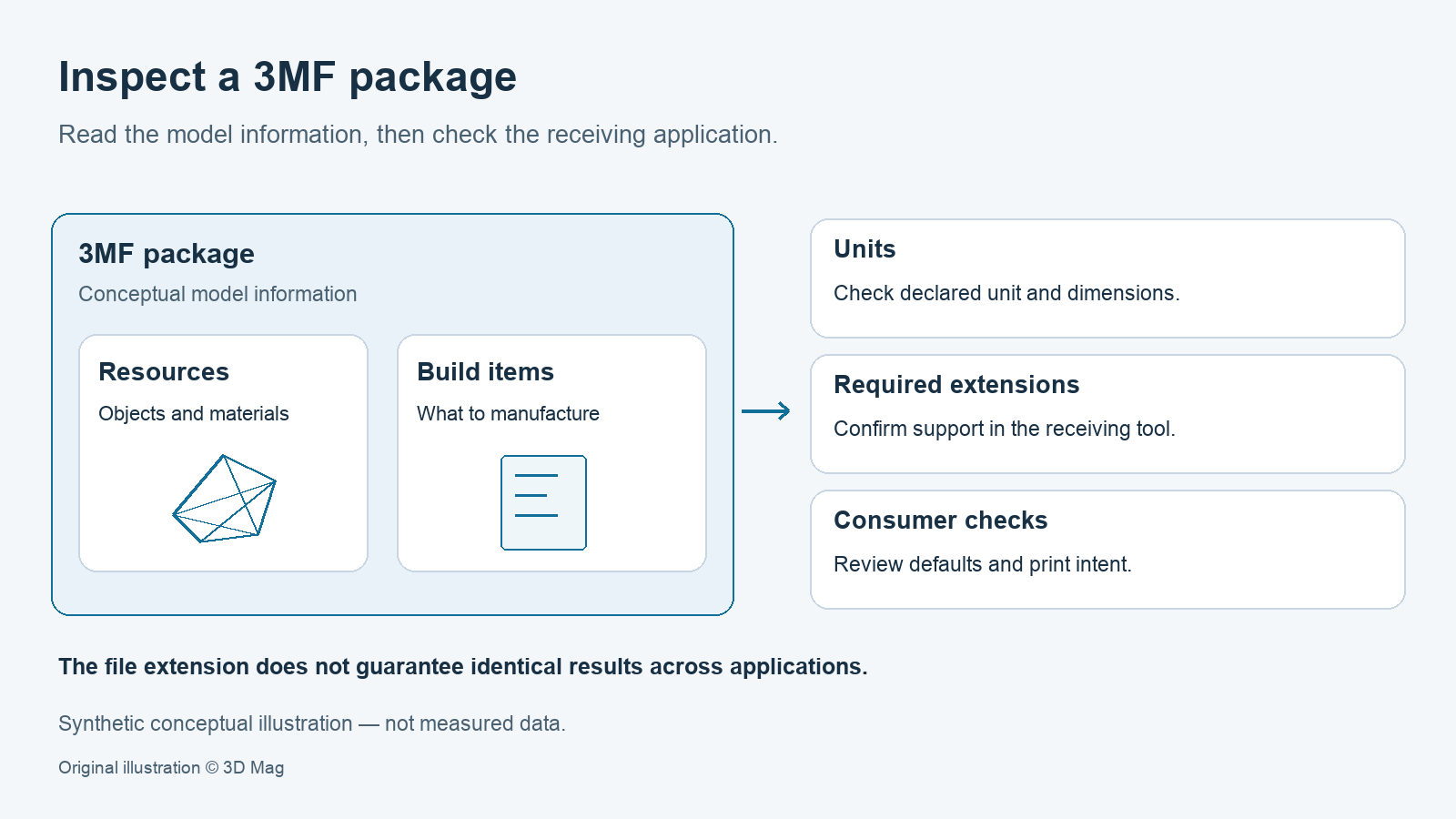
Artec Studio tech specs list CAD import formats including STEP/STP, IGES/IGS, SAT, XT, and XB, with CAD export for STEP, IGES, and XT. Spider II’s own output list groups exports the same way: OBJ, PLY, WRL, STL, AOP, ASC, PTX, E57 and XYZRGB for mesh-style output, STEP, IGES and X_T for CAD, and CSV, DXF and XML for measurements. A STEP file can therefore be useful, editable enough, or nearly dead geometry depending on how it was generated. File extension alone does not tell you whether the body contains clean B-rep surfaces, lightly remodeled solids, or just imported geometry with little design intent. [7] [1]
Spider II vs Eva vs the legacy Space Spider
All three scanners can support a 3D scanner for CAD workflow, but only two of them are current products, and their vendor-published up-to specs point to different object sizes, pass counts, and operator burdens. The key variables are working distance and field of view: a smaller field of view usually means more passes and more global registration effort on larger parts, while higher capture speed can reduce operator fatigue without making CAD reconstruction automatically correct. [1] [3] [5]
| Scanner | Status | Best-fit object class | Key vendor-published specs | Main workflow caveat |
|---|---|---|---|---|
| Artec Spider II | Current | Small, detailed parts at close range | Up to 0.05 mm accuracy; up to 0.05 mm resolution; 0.05 mm + 0.3 mm/m over distance; 0.19–0.3 m; 128 × 104 mm to 171 × 152 mm; 1,800 cm³; up to 30 fps; up to 8 mln points/s; 5 MP texture; 0.95 kg. [1] | The finest detail in the range, but the short working distance still forces more passes on anything that outgrows the capture zone, and Artec reserves the right to update specifications. [1] |
| Artec Eva | Current | Larger objects and broader coverage | Up to 0.1 mm accuracy; up to 0.2 mm resolution; 0.1 mm + 0.3 mm/m over distance; 0.4–1 m; 214 × 148 mm to 536 × 371 mm; 61,000 cm³; up to 16 fps; up to 18 mln points/s; 1.3 MP texture; 0.9 kg. [5] | Bigger capture zone reduces pass count on larger parts, but fine-detail CAD work is less forgiving than with Spider II. [5] |
| Artec Space Spider | Legacy / discontinued | Small, detailed parts — if you already own one | Up to 0.05 mm accuracy; up to 0.1 mm resolution; 0.2–0.3 m; 90 × 70 mm to 180 × 140 mm; up to 7.5 fps; up to 1 mln points/s; 1.3 MP texture; 0.85 kg. [3] [4] | Artec labels it a legacy scanner and points to Spider II as its successor; Artec Studio still supports it, but it is not a current purchase path. [3] [7] |
Spider II is the closest fit when the geometry is small, detailed, and close-range, and it is now the only current Artec scanner in that class. Eva is the practical choice once the object grows enough that a larger field of view matters more than the last increment of fine detail. Neither choice guarantees CAD correctness by itself: speed helps the operator, while reconstruction quality still depends on registration, fusion, and remodeling. [1] [5]
Validation — how to prove your scan-to-CAD output is good enough
Validation is job-specific acceptance, not a property you inherit from the scanner spec. A part can scan well and still fail the project if the reconstructed CAD body does not satisfy the functional features you actually care about — bores, planes, patterns, mating faces, or other datums. The right question is not whether the scan looked clean, but whether the scan-to-CAD output is good enough for the intended use. [10] [15]
The usual checks are deviation maps, datum strategy, and reference measurements. Deviation analysis shows where the mesh or CAD body departs from the source data; datum strategy keeps those deviations anchored to the features that matter; and reference measurements give you an independent sanity check. On the metrology side, ISO 10360-13 covers acceptance and reverification tests for optical 3D CMS length measurement performance, while the preview notes that less cooperative surfaces and added or omitted conditions can affect how well test results predict real performance. NISTIR 7054 discusses ball plates and ball bars and recommends evaluating how the system combines multiple vantage points. [10] [11] [13]
Peer-reviewed work on the Spider family is worth reading with the generational change in mind. A 2024 Scientific Reports study on facial surface imaging notes that the manufacturer’s published validity work used scale ball bars, and warns that a narrow field of view can require many small stitched images on larger regions — a caution that studied Space Spider but still applies to Spider II, whose capture window is only modestly larger. [15]
For reference measurements, calipers, micrometers, and a CMM can all be part of the workflow, depending on the feature and the required confidence. If you need inspection-grade or traceable claims, use calibrated artifacts and a controlled setup rather than relying on the scanner’s headline accuracy alone. That is the point where CAD-ready geometry becomes an evaluated engineering deliverable instead of a visually convincing mesh. [13]
Standards and “metrology-grade” language
ISO 10360-13, published in September 2021, addresses optical 3D coordinate measuring system length measurement performance. That is useful context, but it does not by itself prove that a specific scanner, scan-to-CAD workflow, or operator setup is fit for a given inspection task. Naming a standard is not the same as certifying a scanner or certifying your reverse-engineering process. The ISO abstract limits the document to cooperative surface conditions, and the preview adds caveats about less cooperative surfaces, added or omitted conditions, and mutual-agreement use for other CMS types. [10] [11]
VDI/VDE 2634 Blatt 2 is listed as withdrawn, with a replacement recommendation pointing to DIN EN ISO 10360-13:2023-11. The DIN listing also notes that its procedures apply to single-view area-scanning systems and do not cover transforming multiple single views into one object coordinate system. That matters for handheld scan workflows that depend on registering multiple views into one model. [12]
Limitations and failure modes
The main surface problems are not unique to Spider II, but they matter more when you are trying to produce CAD-ready geometry from a mesh. Deep, dark, shiny, and concave areas are harder for structured-light systems, and NIST notes that a theoretical resolution value does not equal the smallest distinguishable feature in real use. That means a scan can look dense while still missing edges, holes, or tight internal detail that the CAD model later depends on. [9]
Workflow choices can make those issues better or worse. Artec guidance notes that reflective or furry objects, along with poor preparation, can hurt registration quality, so the limitation is often the combination of surface, setup, and scan path rather than the scanner alone. On larger parts, a narrow field of view can force many small captures to be stitched together, which increases the chance of registration drift and accumulated error across the part. The 2024 Scientific Reports study makes that point explicitly for larger facial regions, and the SCITEPRESS assessment highlights how difficult low-feature objects can be in a Spider-class workflow. [8] [15] [16]
There is also a practical constraint that is easy to miss on a spec sheet: Spider II is tethered to a Thunderbolt 4 host and runs on a DC 24 V adapter, and Artec’s recommended configuration is a 13th- or 14th-generation Intel Core i7 or i9 with an RTX 4070 8 GB, with a 12th-generation Core i9 and an RTX 4060 8 GB as the minimum. Supported operating systems are Windows 10 x64 and Windows 11. That is a workstation-class requirement, not a laptop afterthought, and it belongs in the budget alongside the scanner. [1]
CAD reconstruction has its own failure modes. If the mesh is noisy, it is easy to over-smooth during fusion or to overfit the CAD model to artifacts instead of the true shape. Thin edges, transparent parts, repetitive low-feature geometry, and poorly constrained freeform regions are all places where reverse engineering can drift away from the real part if the operator treats the mesh as cleaner than it is.
Buying and selection reality in 2026
In 2026 the practical choice is between a new Spider II, an Eva if the object is larger, and — only as a second-hand or already-owned option — a Space Spider. Artec’s legacy page is explicit that Space Spider has a successor, and the Artec Studio specifications page places it among discontinued models, so the used market is the only route to one. That is a real option for a shop with a fixed budget, but it comes with the usual second-hand caveats: no current warranty path, and half the resolution figure of the scanner that replaced it. [3] [7]
Spider II itself ships with a 2-year warranty and is specified for Windows 10 x64 and Windows 11. The main toolchain context is that Hexagon completed the Geomagic acquisition on April 2, 2025, and described the suite around bringing 3D measurement data into CAD workflows, including parametric scan-to-CAD. That matters less for scanner choice than for what happens after capture: surfacing, inspection, and CAD reconstruction still need to fit the downstream software chain. [1] [17]
Practical recommendation — is Artec Spider II the best 3D scanner for CAD modeling?
Artec Spider II is the strongest choice in Artec’s range when the part is small, detailed, and close-range, and the operator is willing to spend time on registration and CAD reconstruction. Its vendor-published up to 0.05 mm accuracy and up to 0.05 mm resolution keep it in the detailed-scanning class, and the jump to 30 fps and 8 mln points/s makes the capture session itself easier to manage. But it is not a universal winner: Eva trades fine-detail headroom for much larger coverage on bigger objects, and neither scanner substitutes for a traceable inspection process. So the real answer is conditional: best for small, detail-heavy reverse engineering, not best for every CAD task. [1] [5]
- Spider II — choose it for small, close-range, detail-heavy reverse engineering. It is the current Artec answer in this class.
- Eva — choose it for larger parts where coverage matters more than the finest detail.
- Space Spider — only relevant if you already own one, or find a well-priced used unit and accept its legacy status.
- Metrology-grade verification route — choose it when acceptance depends on controlled, traceable inspection rather than just CAD-ready geometry.
FAQ
1. Is Artec Spider II good for scan to CAD?
Yes. For small, detailed, close-range parts it is a strong fit for reverse engineering, and it is the current scanner in Artec’s high-detail handheld class. Its vendor-published local specs are up to 0.05 mm accuracy and up to 0.05 mm resolution, but that does not make it universally best for every CAD job. The result still depends on registration, fusion, and how carefully you rebuild the CAD model. [1]
2. Is the Artec Space Spider still available?
No, not as a new product. Artec’s own page for the model states that Space Spider is a legacy scanner and directs readers to its successor, Artec Spider II. Artec Studio still lists it among discontinued models that remain compatible with the software, so existing units keep working, but new purchases go through Spider II or the used market. [3] [7]
3. Does STEP/IGES/X_T export mean the model is fully editable parametric CAD?
No. Artec Studio’s CAD support centers on CAD objects, primitives, and freeform surfacing rather than guaranteed feature-history parametric CAD. A STEP, IGES, or X_T file may be useful, lightly editable, or close to dead geometry depending on how it was created. File extension alone does not tell you whether design intent survived. [6] [7]
4. What’s the difference between a mesh, NURBS surfaces, and a B-rep solid in scan-to-CAD?
A mesh is a triangle surface built from scan data. NURBS surfaces are smooth mathematical patches often used to reconstruct freeform geometry. A B-rep solid defines a body by its faces, edges, and vertices. In scan-to-CAD work, you usually move from mesh to surfaces, then to a solid if the downstream CAD task needs a proper editable body.
5. Spider II vs Eva: which is best for reverse engineering?
It depends on part size. Spider II is the close-range detail option, with up to 0.05 mm resolution, a 0.19–0.3 m working distance and a 1,800 cm³ capture zone. Eva is the larger-object choice, with 0.4–1 m working distance and a 61,000 cm³ volume capture zone but looser fine-detail figures at up to 0.1 mm accuracy and up to 0.2 mm resolution. Small and intricate goes to Spider II; large and forgiving goes to Eva. [1] [5]
6. How do you validate scan-to-CAD accuracy without inventing tolerances?
Use job-specific acceptance criteria tied to real features — for example bores, planes, or mating patterns — and check them with deviation maps, datum strategy, and reference measurements. Calipers, micrometers, or a CMM can help, depending on the feature. If you need traceable claims, use calibrated artifacts and controlled conditions instead of assuming the scanner spec is the part tolerance. [10] [11] [13]
7. Why do shiny/dark/deep features break structured-light workflows, and what mitigations actually help?
Structured light struggles when projected patterns do not return cleanly from the surface or geometry. Shiny, dark, deep, and concave features are common problem areas. Practical mitigations are surface prep, temporary markers where needed, fixturing, better scan angles, and stable lighting. Those steps improve capture and registration, but they do not turn a difficult surface into an easy one. [9] [8]
8. Does citing ISO 10360-13 prove my scanner/workflow is inspection-grade?
No. ISO 10360-13, published in 2021, is a method and scope reference for optical 3D coordinate measuring system length measurement performance. It helps frame acceptance and reverification, but it does not certify a specific scanner, operator, or reverse-engineering workflow. Inspection-grade status still depends on your actual setup, artifacts, and acceptance criteria. [10] [11]
Related on 3D Mag
- Artec Spider II: the best 3D scanner for car parts
- Artec Spider II: the best 3D scanner for prosthetics and orthotics
- How easy is it to get from 3D scan to CAD?
Sources
- Artec Spider II product page and tech specs
- Artec Spider II press release
- Artec Space Spider legacy product page (successor notice)
- Artec Space Spider brochure (PDF)
- Artec Eva product page
- Artec Studio 19 docs: Working with CAD objects
- Artec Studio tech specs (supported and discontinued scanners)
- Artec Support: Max error / Quality value
- NIST: Sources of Errors in Structured Light 3D Scanners (PDF)
- ISO 10360-13:2021 abstract page
- ISO 10360-13:2021 preview (PDF)
- VDI/VDE 2634 Blatt 2 listing (withdrawn; replacement note)
- NISTIR 7054 (PDF): Calibration of Structured Light Metrology Systems
- Develop3D review: Artec Eva & Space Spider
- Scientific Reports: Reliability and validity of handheld structured light scanners and a static stereophotogrammetry system in facial three-dimensional surface imaging
- SCITEPRESS (PDF): Precision Assessment of Artec Space Spider…
- Hexagon press release: Geomagic acquisition completed
- VIM3 definition: Measurement accuracy
- VIM3 definition: Measurement precision
- VIM3 definition: Measurement repeatability