
Summary
FDM vs SLS is mainly a choice between material extrusion and polymer laser-based powder bed fusion, which current standards and NIST treat as separate additive manufacturing process families. [1] [2] [9] For many users, FDM offers a simpler filament-based workflow that often relies on printed supports, while SLS is often better suited to support-free packing of more complex nylon parts in a powder bed. [19] [20] The better option depends on geometry, material, batch density, post-processing, and the cost logic of your workflow.
FDM vs SLS: Quick Answer
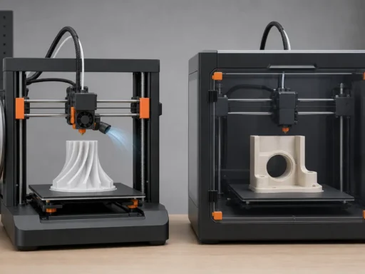
FDM vs SLS is shorthand for comparing material extrusion with polymer laser-based powder bed fusion. [1] [2] [9] As a first-pass rule, choose FDM or material extrusion for a lower-friction starting workflow and simpler single-part iteration in many cases, and choose SLS when support-free packing and batch nesting of nylon parts are central to the job. [19] [20]
The split is usually geometric and operational rather than ideological. FDM builds from thermoplastic filament and often needs printed supports for overhangs, while SLS builds inside a powder bed that can support many features without dedicated supports on compact commercial systems such as the cited Fuse 1 example. [17] [19]
Biggest practical differences
- Process family: FDM belongs to material extrusion, while SLS here refers to polymer laser-based powder bed fusion. [1] [2] [9]
- Naming: FDM is common user shorthand, but material extrusion is the standards-friendly category name. [1] [2]
- Feedstock: FDM uses thermoplastic filament, while SLS uses polymer powder feedstock. [17] [19]
- Support strategy: FDM often uses printed supports, while SLS often builds without dedicated supports because surrounding powder supports the part. [19]
- Typical post-processing: FDM often means support removal, while SLS usually means cooldown, excavation, and depowdering. [19]
What the Terms Mean
FDM, FFF, and material extrusion
In standards language, material extrusion is the additive manufacturing category in which material is selectively dispensed through a nozzle or orifice, while powder bed fusion is a different umbrella category. [1] [2] In everyday use, many people say FDM for filament-based plastic printing, and many open-machine users also say FFF for the same broad approach. NIST IR 8059 notes that fused deposition modeling originally denoted Stratasys machines, while material extrusion is the generic process term. [3] That distinction matters because current qualification language for polymer AM is written around part properties and process families, not around one brand-derived label. [7]
SLS and polymer powder bed fusion
In this article, SLS means polymer laser-based powder bed fusion. ISO/ASTM 52936-1 states that PBF-LB/P is commonly known as laser sintering, and ASTM F3281 / ISO/ASTM 52911-2 is the design-standard anchor for this process family. [9] [10] MJF, SAF, binder jetting, and metal laser powder bed fusion are adjacent but different named process families, so they are outside this comparison. [1] [2] [23] [24]
What counts as a functional part?
- visual model
- fit-check prototype
- functional prototype
- end-use / production aid
For this article, functional parts means load-bearing or use-tested housings, clips, jigs, fixtures, ducts, snap-fit parts, brackets, and low-volume end-use nylon components where geometry, environment, and validation level matter. [7]
How FDM and SLS Work
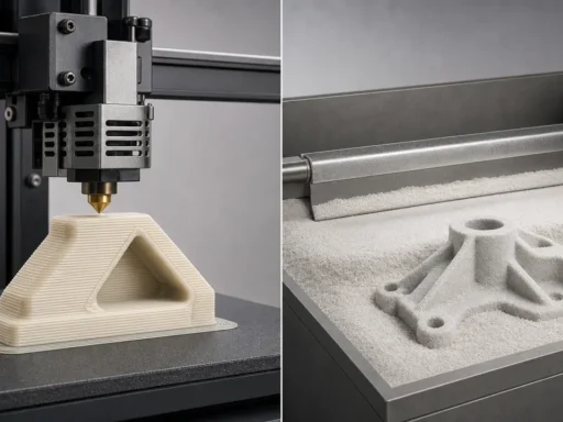
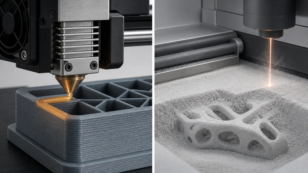
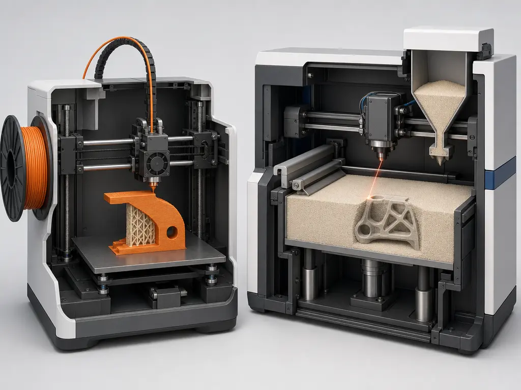
In fused deposition modeling, or more generically material extrusion, the machine feeds thermoplastic filament into a heated print head, softens or melts it, and pushes it through a nozzle as a narrow road of material. The nozzle moves in X-Y while the machine steps upward in Z, and each deposited bead cools and bonds to adjacent roads and to the layer below. Overhangs often require printed support structures that are later removed. As one machine-specific example, the Stratasys F170 brochure lists a 254 × 254 × 254 mm build tray and layer options of 0.330, 0.254, 0.178, and 0.127 mm. [17]
In selective laser sintering as used here, the machine spreads a thin polymer powder layer across the build area and a laser exposes the selected regions for that slice. Fresh powder is spread, the next cross-section is scanned, and the part grows inside the powder bed. A key difference is that surrounding unsintered powder supports many overhangs and enclosed forms during the build, which reduces the need for dedicated support structures but does not remove packing, thermal, or powder-removal constraints. After printing, the full build usually cools in the powder cake before parts are excavated and depowdered. On one compact SLS example, the build volume is 165 × 165 × 300 mm, the layer thickness is 110 microns, the laser spot size is 200 microns FWHM, and the support strategy is listed as “No supports.” [19]
| Process step | FDM/material extrusion | SLS | Why it matters |
|---|---|---|---|
| Feedstock delivery | Filament is driven into a heated nozzle. [17] | Powder is spread in thin layers across a bed. [19] | Feedstock form changes handling, storage, and machine design. |
| Layer formation | Extruded beads are placed along toolpaths and cool into shape. [17] | A laser exposes selected powder regions within each spread layer. [19] | The consolidation mechanism affects surface character and bonding behavior. |
| Support during build | Printed supports are often needed for overhangs. [17] | Surrounding powder supports many features without dedicated supports. [19] | Geometry freedom and finishing effort change significantly. |
| After printing | Support removal is usually part of finishing. [17] | Cooldown and depowdering are major steps. [19] | Real workflow time includes more than the moment of printing. |
Materials, Mechanics, and What “Functional” Means
For material extrusion, the first materials question is not what exists in the market, but what your exact machine, nozzle, chamber, and validated settings can actually run. Many users encounter PLA, ABS, PETG, nylon, TPU, and filled variants on open systems, while industrial platforms usually qualify narrower material sets with defined settings and support combinations. That means two printers both described as “FDM” can differ substantially in usable polymers and documented properties.
For polymer laser-based powder bed fusion, PA12 is the main reference material in current qualification guidance, with PA11 as a secondary reference. ISO/ASTM 52925 states that its parameters and recommendations relate mainly to PA12, make references to PA11, and are not applicable to other polymeric materials in general. [8] As a material-specific example rather than a universal SLS value, Formlabs reports for Nylon 12 Powder an ultimate tensile strength of 50 MPa, tensile modulus of 1900 MPa, and elongation at break of 11% in X/Y and 6% in Z under ASTM D638-14 Type 1. [21]
Three terms should stay separate. Strength is the stress level associated with yielding or breaking, depending on the reported metric. Stiffness is resistance to elastic deformation and is commonly reported as modulus. Elongation is how much a specimen stretches before failure. ASTM D638 notes that tensile properties vary with specimen preparation, speed, and test environment, so cross-source comparisons require caution. [6] Stratasys states that FDM parts are anisotropic, and its ABS-M30 Black data for an F900 at 0.254 mm layer height report ASTM D638 yield strength values of 30.8 MPa in XZ and 27.5 MPa in ZX. [22] SLS also shows anisotropy and machine-to-machine variability in PA12 round-robin work, and broader reviews find anisotropy across polymer AM methods generally. [12] [13]
Before calling a part functional, specify
- load case
- environment
- geometry
- validation level
Geometry, Supports, and Design Rules That Change Real Outcomes
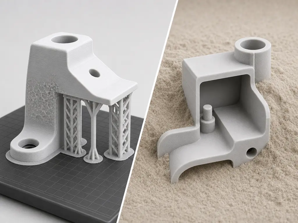
Geometry is where the workflow difference becomes concrete. In material extrusion, support strategy strongly affects orientation, accessible overhangs, internal channels, and how much finishing is needed later. Industrial FDM workflows therefore rely on design guides rather than trial and error alone. In SLS, surrounding powder supports many features during the build, and the cited compact Formlabs system explicitly lists “No supports.” [19] That creates more support-free freedom, especially for nested parts and shapes that would be awkward to scaffold in material extrusion, but the tradeoff shifts toward packing, powder removal, and heat management. [20]
The design-rule logic also differs. For FDM, wall thickness is linked to slice thickness and deposition strategy rather than to one universal minimum. One industrial guide recommends minimum walls of 0.508, 0.72, 1.00, 1.32, and 2.54 mm for 0.127, 0.18, 0.25, 0.33, and 0.508 mm slices, and summarizes the rule as roughly four times slice thickness. [18] The same guide says holes are generally fractionally undersized, so critical holes may be bored or reamed after printing. [18] For the cited Fuse Series SLS guidance, baseline rules include 0.6 mm vertical walls, 0.3 mm horizontal walls, 0.8 mm minimum pin or wire diameter, 1.0 mm minimum hole size, recommended 3.5 mm drain holes with at least two openings for enclosed cavities, and recommended 5 mm spacing between separate parts to reduce thermal warping effects. [20]
More support-free freedom does not mean unlimited freedom. SLS still has constraints from powder evacuation, feature fragility, and chamber packing, while FDM can still succeed on demanding parts when geometry and orientation are designed around the process. [18] [20]
Design-rule differences that matter in practice
- FDM wall-thickness sensitivity: minimum walls often scale with slice thickness and road strategy. [18]
- FDM holes running undersized: printed holes are often fractionally undersized and critical ones may need machining. [18]
- FDM support-interface scars / orientation tradeoff: supports can leave witness surfaces, so orientation becomes a surface-versus-access compromise. [18]
- SLS minimum walls: the cited Fuse Series guidance uses 0.6 mm vertical walls and 0.3 mm horizontal walls as baseline recommendations. [20]
- SLS minimum holes and pins: the same guide recommends 1.0 mm minimum holes and 0.8 mm minimum pin or wire diameter. [20]
- SLS drain-hole requirement for enclosed cavities: enclosed volumes need powder escape, with at least two recommended 3.5 mm drain holes. [20]
- SLS part spacing / packing heat effects: separate parts are recommended to be at least 5 mm apart to reduce neighboring thermal effects. [20]
Accuracy, Repeatability, and Surface Finish
Claims about “better accuracy” in additive manufacturing need method context. ISO/ASTM 52902 frames geometric capability through test artefacts, and ASTM F2971 emphasizes reporting the preparation, processing, and post-processing history of AM specimens. [4] [5] Independent comparison work on polymer systems also shows that dimensional capability is benchmark-dependent and system-specific rather than a fixed property of “FDM” or “SLS” as categories. [11]
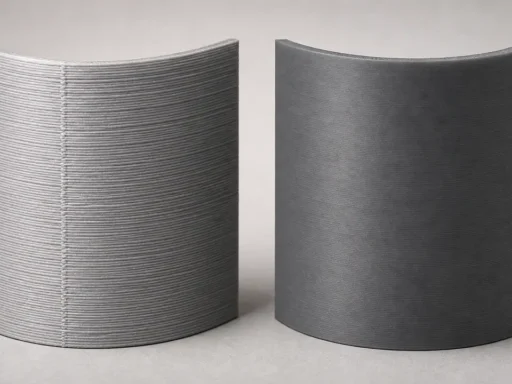
It helps to separate ideas that are often blended together. Dimensional accuracy is closeness to the intended size. Repeatability or precision is how consistently a machine reproduces a result. Layer stepping is the visible stair-step effect on sloped surfaces. Surface finish depends on the as-printed texture and the finishing route. As-printed FDM may show visible layer lines and support marks, while as-printed SLS may avoid support scars but keep a matte, slightly granular surface. Example hardware numbers such as 110-micron layers or a 200-micron FWHM laser spot describe process settings, not guaranteed dimensional accuracy. [19]
ASTM D638 is a tensile standard rather than a dimensional one, but it still offers a useful caution: measured properties change with specimen preparation, speed, and environment. [6] The same discipline applies to geometry claims. If someone cannot tie an accuracy claim to a defined artefact, method, geometry, machine, and material, the fair answer is No reliable universal figure found. [4] [11]
| Metric | FDM tendency | SLS tendency | Caveat |
|---|---|---|---|
| layer height | Often discussed through selectable slice settings. [17] | The cited Fuse 1 example uses 110 microns. [19] | Layer height affects stair-stepping and build time, not accuracy by itself. [4] |
| nozzle / laser spot size | Nozzle diameter shapes deposited roads. | The cited Fuse 1 example lists a 200 micron FWHM laser spot. [19] | Tool size or beam size is not a direct tolerance guarantee. [4] [11] |
| dimensional accuracy | Can be good on suitable geometries and tuned systems. | Can be good on suitable geometries and tuned systems. | Comparison requires a benchmark artefact and method. [4] [11] |
| repeatability / precision | Depends on machine control, material condition, and workflow discipline. | Depends on powder condition, thermal control, and workflow discipline. | Precision is not the same as nominal accuracy. [4] [5] |
| surface finish | As-printed, often shows layer lines and possible support marks. | As-printed, often avoids support scars but may retain a matte, granular texture. | Do not rank a single winner without stating the as-printed or post-processed condition. |
No reliable universal figure found. [4] [11]
Workflow, Throughput, and Cost Logic
Which is cheaper: FDM or SLS? FDM is usually cheaper at entry level and for many simple parts; SLS can become more economical for dense batches of complex nylon parts. [19] [20] That is a workflow conclusion, not a universal machine-price law.
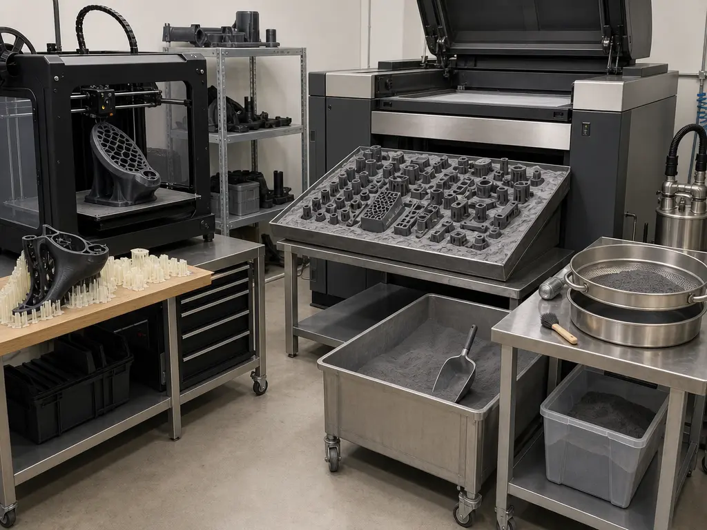
The cost drivers sit in different places. For FDM, cost often grows with support material, orientation compromises, and manual cleanup. For SLS, one build can contain many parts inside the cited 165 × 165 × 300 mm example volume, and the absence of dedicated supports changes nesting logic and labor distribution. [19] But SLS adds its own costs in powder handling, cooldown delay, depowdering, and cavity-management rules. On the cited Fuse 1 example, material refresh is 30%–50%. The matching design guide recommends at least two 3.5 mm drain holes for enclosed cavities and about 5 mm spacing between separate parts for high-quality results. [19] [20]
So the real comparison is not “cheap versus expensive.” It is whether your workflow is dominated by single-part simplicity, or by the ability to fill a powder-bed build with many complex parts and amortize the handling overhead across the batch. [19] [20]
| Cost bucket | FDM tendency | SLS tendency | When it flips |
|---|---|---|---|
| capital equipment | Often lower barrier to entry. | Often higher workflow barrier. | It flips when batch throughput justifies the platform. |
| consumables | Filament and support use scale with part and orientation. | Powder workflow includes refresh and reuse logic, with one cited example listing 30%–50% refresh. [19] | It flips when many parts share one build efficiently. |
| labor | Setup can be simple, but support removal adds hands-on time. | Nesting, cooldown, and depowdering add separate workflow steps. [19] | It flips when FDM support cleanup dominates job time. |
| post-processing equipment | Often lighter for simple parts. | Usually needs a depowdering workflow. [19] | It flips when powder handling is justified by batch output. |
| batch density / packing | Parts compete for tray area and support clearance. | Dense packing is a core advantage, within spacing rules such as about 5 mm between separate parts. [20] | It flips on mixed or complex batches. |
| cooldown delay | Often shorter path from print end to handling. | Full-build cooldown can delay part access. [19] | It flips when response time matters more than nesting efficiency. |
| support removal / powder handling | Dedicated supports often need removal. | No dedicated supports on the cited Fuse 1 example, but powder handling remains. [19] | It flips when supports are numerous or hard to access. |
When to Choose FDM vs When to Choose SLS
The practical way to decide is to match the process to the job, not to ask which one is better in the abstract. Validated industrial FDM workflows can be a strong fit for many fixtures, housings, and shop-floor tools, while SLS becomes attractive when the build benefits from support-free packing, nylon-centric properties, and many parts sharing one cycle. Example platform sizes also influence the choice: the cited F170 lists 254 × 254 × 254 mm, while the cited Fuse 1 lists 165 × 165 × 300 mm and “No supports.” [17] [19]
| Scenario | Better fit | Why | Watch-out |
|---|---|---|---|
| concept models | FDM | Usually simpler for quick visual or fit iterations. | Support cleanup and visible layer lines can affect presentation. |
| low-cost fixtures | FDM | Validated industrial material-extrusion workflows often suit jigs and fixtures well. [22] | Orientation still affects in-use performance. [22] |
| large prototype housings | FDM | The cited F170 tray size can favor larger single parts. [17] | Large flat parts still need careful orientation and support planning. |
| nested small-batch nylon parts | SLS | Packing many parts into one powder-bed build is a core advantage. [19] [20] | Cooldown and depowdering still add time. [19] |
| interlocking or internal-feature designs | SLS | Powder support helps with shapes that would be awkward to scaffold. [19] | Internal cavities still need powder escape planning. [20] |
| low-volume end-use polymer parts | SLS or FDM, case-dependent | SLS often fits complex nylon batches, while industrial FDM can also fit validated applications. [21] [22] | Do not compare unlike property types or assume one data sheet covers every part. |
Choose FDM if… you need quick concept models, low-cost fixtures, larger single housings, or a workflow already built around validated material-extrusion setups.
Choose SLS if… you need nested small-batch nylon parts, interlocking geometries, or low-volume end-use parts where support-free packing and batch density matter. [19] [20]
The exceptions matter. A Nylon 12 SLS data sheet reporting 50 MPa ultimate tensile strength and 11% X/Y versus 6% Z elongation at break does not automatically beat an FDM ABS-M30 result reporting 30.8 MPa versus 27.5 MPa yield strength, because those are different materials and different property types. [21] [22] What those examples do show is that geometry-specific validation still decides the final choice. [21] [22]
What the Standards Change in Real Comparisons
The main effect of standards is not to declare a winner, but to make vague claims harder to defend. ISO/ASTM 52924 classifies part-property expectations for thermoplastic polymer parts produced by powder bed fusion or material extrusion, and ASTM F3281 / ISO/ASTM 52911-2 anchors polymer laser-PBF design guidance. [7] [10]
That changes buying decisions in practical ways. ISO/ASTM 52925 makes clear that current polymer laser-PBF feedstock qualification guidance mainly addresses PA12, with references to PA11, rather than every possible SLS polymer. [8] ASTM F2971 also requires reporting enough material, process, and post-processing history for AM test specimens that headline numbers can be judged in context. [5] Standards do not give a universal winner, but they do make comparisons more disciplined.
Short History, Standards, and Qualification Context
The two processes entered industry through different technical lineages. The foundational patent associated with fused deposition modeling traces to Scott Crump, with a priority date of 1989-10-30, while the selective-sintering patent record for Carl Deckard lists a prior-art date of 1986-10-17. [14] [15] The University of Texas at Austin places SLS development in the 1980s in Joe Beaman’s laboratory with Carl Deckard and guidance from Dave Bourell. [16]
For current comparisons, standards matter more than origin stories. ISO/ASTM 52900 anchors the vocabulary that separates AM categories, ISO/ASTM 52924 frames polymer part-property classification, and ISO/ASTM 52936-1 places laser sintering within the PBF-LB/P context. [1] [7] [9] ISO/ASTM 52925 adds an important scope limit by noting that current feedstock qualification guidance mainly relates to PA12, with references to PA11. [8] The practical takeaway is simple: use the right names, ask for qualified data, and compare processes at the part level.
FDM vs SLS: Final Decision Checklist
FDM vs SLS should be decided by part requirements and workflow constraints, not by a single headline about strength, accuracy, or cost. A useful rule still holds: material extrusion often fits lower-friction entry and many simpler parts, while SLS often fits support-free complex nylon batches. On the cited Fuse 1 example, the support strategy is listed as “No supports,” but enclosed cavities still need planned powder escape. [19] [20]
Before you choose, make sure the comparison is evidence-based. If someone offers a universal accuracy claim without a defined artefact or benchmark, the right answer is No reliable universal figure found. [4] [11] If someone offers a mechanical claim, check the property type, material, machine, orientation, and test method. The earlier Nylon 12 and ABS-M30 examples show why that context matters. [21] [22]
- geometry complexity
- required material family
- mechanical directionality
- batch size
- post-processing tolerance
- internal cavities / powder evacuation
- budget and labor
FAQ
What is the difference between FDM and SLS?
FDM usually means filament-based material extrusion, while SLS here refers to polymer laser-based powder bed fusion. They are separate additive manufacturing technology areas, not two names for the same process. FDM builds by extruding thermoplastic through a nozzle, while SLS builds in a powder bed where surrounding powder supports many features during the build. [2] [19]
Is SLS stronger than FDM?
Not universally. The result depends on machine, material, geometry, and orientation. Stratasys explicitly describes FDM parts as anisotropic and reports orientation-specific ABS-M30 yield values on an F900, while SLS PA12 studies also report anisotropy and machine-to-machine variability. [12] [21] [22]
Is SLS more accurate than FDM?
No reliable universal figure found. [4] [11] Accuracy comparisons need a defined artefact, method, geometry, machine, and material. Independent work shows geometric capability is system-specific and benchmark-dependent, and example settings such as 110-micron layers or a 200-micron laser spot should not be treated as a universal dimensional-accuracy guarantee. [11] [19]
Which is cheaper: FDM or SLS?
FDM is usually cheaper at entry level and for many simple parts; SLS can become more economical for dense batches of complex nylon parts. [19] [20] The reason is workflow structure: FDM often pays in supports and cleanup, while SLS pays in powder handling, cooldown, and depowdering. Support-free building does not make the overall SLS workflow cost-free. [19]
Can FDM make end-use parts?
Yes, in validated cases. The result depends on machine, material, geometry, and orientation. ISO/ASTM 52924 frames qualification around part properties, and Stratasys’ ABS-M30 data show clear orientation sensitivity in FDM parts. [7] [22] That means end-use acceptance should be tied to validation and use case, not to the process name alone.
Expert: Why do SLS parts still need drain holes and packing rules if there are no supports?
Because “no supports” does not mean “no trapped powder” or “no thermal constraints.” The cited Fuse Series guidance recommends at least two drain holes of 3.5 mm for enclosed cavities and about 5 mm spacing between separate parts for high-quality results. [19] [20] SLS removes dedicated supports for many geometries, but it does not remove depowdering and packing rules.
Expert: What test details must be reported before comparing mechanical data from FDM and SLS parts?
At minimum, report the material, process, and post-processing history, because ASTM F2971 treats those as core reporting elements for AM specimens. [5] You also need the test method and conditions, and in practice the machine or system, orientation, and exact property type. ASTM D638 warns that specimen preparation, speed, and environment affect tensile results. [6]
Sources
Citations in the article must appear as sentence-ending references in the format [n].
- ISO/ASTM 52900:2021 Additive manufacturing — General principles — Fundamentals and vocabulary
- NIST Additive Manufacturing Technologies
- NIST IR 8059 Materials Testing Standards for Additive Manufacturing of Polymer Materials
- ISO/ASTM 52902:2023 Additive manufacturing — Test artefacts — Geometric capability assessment of additive manufacturing systems
- ASTM F2971-13(2021) Standard Practice for Reporting Data for Test Specimens Prepared by Additive Manufacturing
- ASTM D638-22 Standard Test Method for Tensile Properties of Plastics
- ISO/ASTM 52924:2023 Additive manufacturing of polymers — Qualification principles — Classification of part properties
- ISO/ASTM 52925:2022 Additive manufacturing of polymers — Feedstock materials — Qualification of materials for laser-based powder bed fusion of parts
- ISO/ASTM 52936-1:2023 Additive manufacturing of polymers — Qualification principles — Part 1: General principles and preparation of test specimens for PBF-LB
- ASTM F3281 / ISO/ASTM 52911-2 Additive manufacturing — Design — Part 2: Laser-based powder bed fusion of polymers
- Minetola, Calignano, Galati, Comparing geometric tolerance capabilities of additive manufacturing systems for polymers
- Schmid et al., A Round Robin study for Selective Laser Sintering of polyamide 12: Microstructural origin of the mechanical properties
- Zohdi and Yang, Material Anisotropy in Additively Manufactured Polymers and Polymer Composites: A Review
- US5121329A Apparatus and method for creating three-dimensional objects
- US5597589A Apparatus for producing parts by selective sintering
- University of Texas at Austin, Selective Laser Sintering, From a Texas Idea to a Global Industry
- Stratasys F170 brochure
- Stratasys Direct FDM Design Guide
- Formlabs Fuse 1 / Fuse Sift Tech Specs PDF
- Formlabs Fuse Series SLS Design Guide
- Formlabs Nylon 12 Powder TDS
- Stratasys ABS-M30 Material Data Sheet
- HP official Multi Jet Fusion page / press release
- Stratasys Direct SAF page