Summary
An IGES file usually means IGES, the Initial Graphics Exchange Specification, an older neutral CAD interchange format used to move model data between dissimilar systems. Autodesk describes IGES as a neutral file format, and NIST distinguishes it from STEP by noting that IGES was developed primarily for the exchange of pure geometric data, while STEP was intended to handle a much wider range of product-related data across the product life cycle. Current vendor documentation also shows ongoing translator support in major CAD ecosystems, including SOLIDWORKS, PTC Creo Elements/Direct, and Siemens NX. [4] [2] [8] [9] [10]
This article explains what IGES is, why it was created, how it works in practice, what it usually carries, where translation risks appear, and why STEP is often preferred when more product structure and lifecycle context must survive exchange. [2] [3]
Why IGES Was Created
IGES emerged because early engineering CAD systems did not interoperate well. Companies could design digitally inside their own software, but exchanging that data across different vendors’ systems was much harder. NIST’s history report says events in 1979 helped catalyze the CAD vendor and user community to create a national standard for CAD data exchange, driven by frustration over the inability to share data among tools and internal databases. [1]
That effort moved quickly. NIST’s history report says the first draft of IGES was released in January 1980 after two critical reviews, and Version 1 was later standardized as ANSI Y14.26M-1981. [1] That speed helps explain why IGES stayed embedded in engineering workflows for so long: it solved a real interoperability problem early through a practical exchange-file approach, rather than requiring every software pair to maintain its own direct translator. [1]
What an IGES File Does in Practice
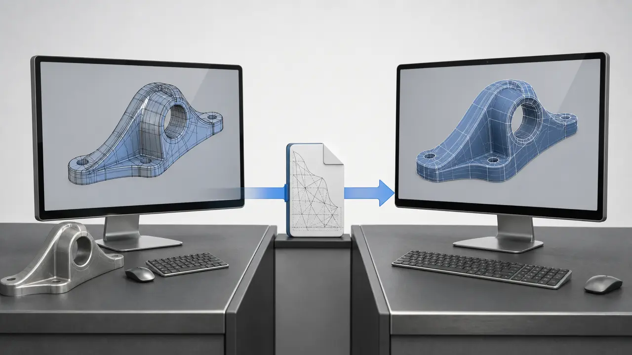
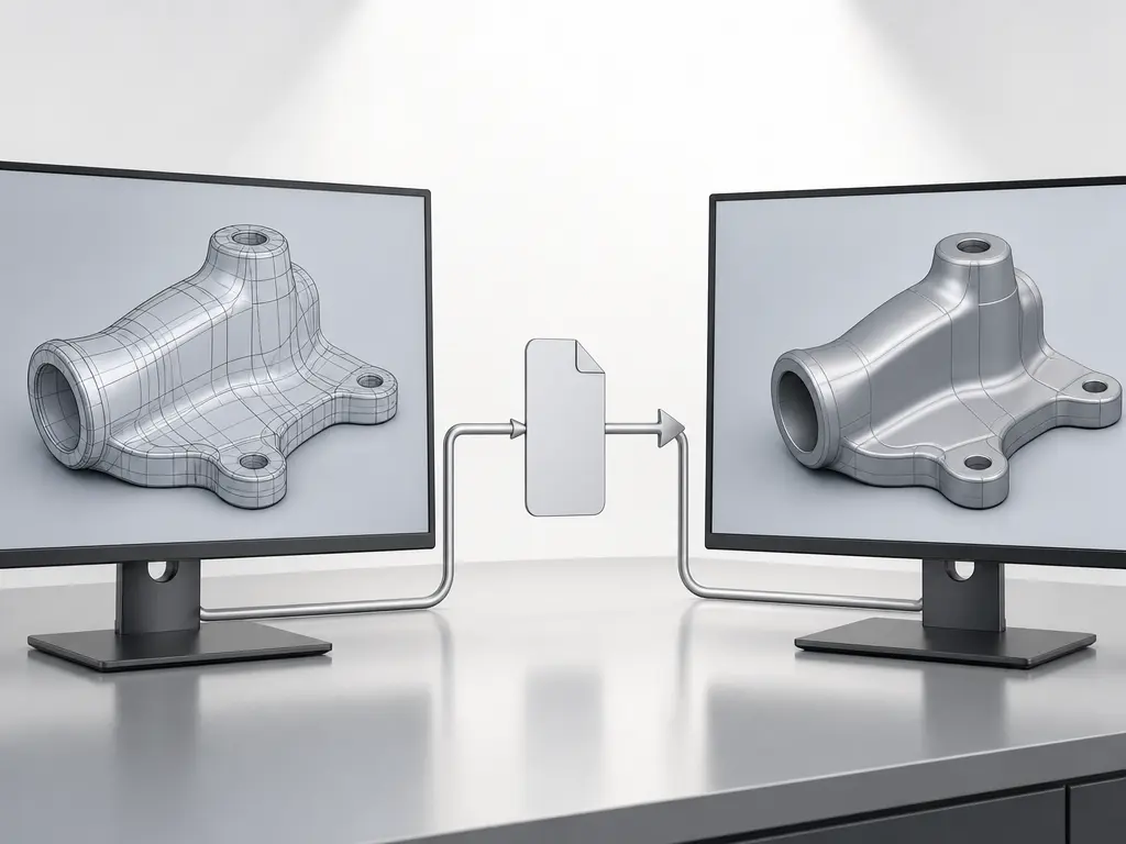
In practice, an IGES file serves as a neutral file format for transferring model data between different systems instead of keeping that data locked to one software vendor’s native format. Autodesk describes IGES as a neutral format designed to transfer 2D and 3D drawing data between dissimilar CAD systems. [4] The format defines an exchange method; each CAD program then decides how completely it reads, writes, repairs, or substitutes the incoming data. [4] [8] [9] [10]
Its role is narrower than “everything about the model moves intact.” NIST describes IGES as having been developed primarily for the exchange of pure geometric data, in contrast to STEP, which was created for a much wider range of product-related data across the life cycle. [2] The safest way to think about IGES is as a geometry-focused engineering CAD interchange format whose usefulness depends heavily on the translators at both ends of the handoff. [2] [4]
How an IGES File Works
At a practical level, the workflow is simple even if the translation details are not. A model is exported from one native CAD system into IGES, then imported into another system that reads the format. The key distinction is between the file’s physical encoding and its logical content: one concerns how the information is stored as text records, while the other concerns how the exchanged entities are organized so CAD software can interpret them. [4] [5]
At the physical level, the IGES standard defines two file formats: fixed-length ASCII and compressed ASCII. In the fixed-length form, information is stored in 80-character records, and Autodesk documents that AutoCAD’s IGES import and export support only this fixed-length form. [4] At the logical level, Autodesk Alias describes a basic five-section structure consisting of Start, Global, Directory, Parameter Data, and Termination. [5] Together, those details make IGES less abstract: it is not just a text file, but a structured exchange file with defined sections and record conventions. [4] [5]
Because IGES is text-based, it is tempting to assume it is easy to read or safely edit by hand. In practice, that is not a reliable assumption. The fixed record lengths, section-based organization, and linked parameter data make the file machine-oriented even when the storage is plain ASCII text. [4] [5] You can open it in a text editor, but being able to see characters is not the same as being able to modify the exchange data without breaking the structure. [4] [5]
What the File Usually Carries
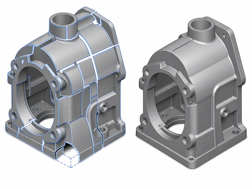
An IGES CAD file typically carries geometry-oriented content, though the exact result depends on translator behavior in the sending and receiving software. At the format level, Autodesk describes IGES as a neutral format for moving 2D and 3D drawing data between dissimilar CAD systems. In translator examples, SOLIDWORKS documentation shows wireframe handling, surface transfer, 3D-curve import, and some B-rep-related behavior. SOLIDWORKS also says it tries to repair imported surfaces when the incoming surface data is not smooth. [4] [6]
Typical content you may see in an IGES file
- Wireframe geometry. [6]
- Curves, including 3D curves in translator-supported workflows. [6]
- Surface geometry and surface-model data. [6]
- Some 2D drawing-type or drafting-style data, depending on what the translator writes and reads. [4]
- Some solid or B-rep-oriented data in workflows where the translator supports that interpretation. [6]
IGES File vs Native CAD Files
Native formats usually retain more design intent and history within the same CAD ecosystem. That advantage comes from staying inside the authoring system’s own feature definitions, model relationships, and edit logic instead of translating them into a neutral exchange form. Autodesk Fusion training materials provide a clear workflow-specific example: imported neutral geometry can open with no timeline, and with no history, sketches, or relationships imported. Autodesk training material also notes that some metadata may be lost when the file is not native to Fusion. [12]
The trade-off is interoperability. A neutral handoff can make geometry accessible across unlike systems, but the receiving system may not reconstruct the original modeling context in the same way. That should not be turned into a universal rule about every CAD package or translator. The safer conclusion is narrower: native formats usually preserve more same-system editability and context, while neutral exchange improves cross-system access when the job is to move usable geometry rather than preserve every part of the original authoring history. [12]
IGES vs STEP
The central distinction is scope. NIST says IGES was developed primarily for the exchange of pure geometric data between CAD systems, while STEP was intended to handle a much wider range of product-related data covering the entire life cycle of a product. [2] That explains more than simply saying STEP is newer.
That broader scope matters because downstream interoperability is not only about shape. It is also about whether receiving software can interpret how a product is structured and controlled. NIST notes that ISO had been working on STEP since 1984, and its description of AP203 says that this STEP application protocol covers product shape models, assembly structure, and configuration control information. [2] [3] STEP was designed to reduce ambiguity about more than geometry alone when data moves through design, manufacturing, and lifecycle processes. [2] [3]
| Format | Main purpose | Scope and context carried | Typical trade-offs |
|---|---|---|---|
| IGES | Neutral geometry exchange | Primarily pure geometric data between CAD systems. [2] | Broad legacy compatibility, but less product context. [2] |
| STEP | Broader product-data exchange | Geometry plus wider product-related data across the lifecycle; AP203 includes product shape models, assembly structure, and configuration control information. [2] [3] | Better semantic continuity, but still dependent on workflow and implementation. [2] [3] |
| Native CAD file | Same-system authoring | Usually retains the richest system-specific editability and design history inside its own ecosystem. [12] | Highest fidelity in-family, weaker cross-platform neutrality. [12] |
For practical decisions, the question is what must survive the handoff. If the transfer is mainly about geometry, IGES may be sufficient. If product structure, controlled configuration, or broader product-data meaning must survive, STEP is usually the better fit. [2] [3]
What Can Go Wrong in IGES Translation
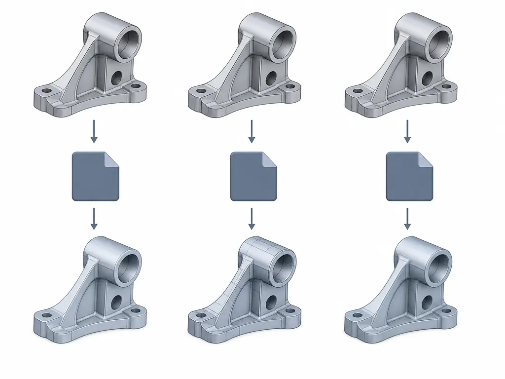
IGES translation problems usually come from differences in how two CAD systems map entities, not from a single dramatic file failure. A sending system may export geometry in one representation, while the receiving system rebuilds it in another, with some detail substituted or simplified. Autodesk explicitly warns that some data will not be preserved in a round trip to IGES and back, and it gives a concrete example in which an exported polyline can come back as a spline after reimport. Autodesk also notes that software support can be narrower than the standard itself: IGES defines fixed-length ASCII and compressed ASCII, but AutoCAD’s IGES tools support only the fixed-length form. [4]
Common translation failure points
- Unsupported entity mappings. [4]
- Curve or surface substitutions. [4]
- Surface gaps or poor trims. [6] [7]
- Failed knitting into usable solids. [6] [7]
- Loss or flattening of design or context data in neutral-file workflows. [12]
Vendor behavior shows how these problems appear in practice. SOLIDWORKS says 3D curves in an IGES file can import as 3D sketch entities, and it says the software tries to repair imported surfaces when the incoming surface data is not smooth. [6] Those are useful translator features, but they also show that the receiving system may be reconstructing or healing data rather than reproducing the original model state exactly. [6]
Surface exchange vs solid formation
Most importantly, sending surfaces is not the same as receiving a watertight solid. In a SOLIDWORKS translator example, the software says that if you want it to try to form a solid from imported IGES data, the source should export trimmed surfaces of entity type 144 or specified untrimmed surface types, and the export should use high precision. [6] SOLIDWORKS also says high trim curve accuracy can sometimes help if the target system has trouble importing the file or cannot knit the surfaces into a useful solid. [7] A surface model may transfer successfully and still need repair before it behaves like a usable solid body in the receiving system. [6] [7]
When an IGES File Still Makes Sense
An IGES file still appears in real engineering CAD work, but in qualified practical scenarios rather than as a universal default. Current documentation shows ongoing translator support in major CAD ecosystems: SOLIDWORKS documents IGES .igs version 5.3 parts or assemblies files, PTC Creo Elements/Direct lists IGES V5.2 and V5.3 import and export support, and Siemens NX lists IGES among its translation formats. [8] [9] [10] That continued availability helps explain why the format persists. It does not mean every system preserves the same semantic depth or reads the same entities with the same fidelity. [8] [9] [10]
Common practical situations where IGES still appears
- Legacy archive or customer-required handoff. Older project libraries and established exchange requirements can keep IGES in circulation where translator support already exists. [8] [9]
- Surface-heavy exchange with older or tool-specific downstream workflows. IGES remains familiar in workflows centered on curves and surfaces rather than rich product structure. [2] [6] [10]
- Geometry handoff where richer product structure is not required. If the goal is mainly to pass shape from one system to another, a geometry-focused neutral format can still be acceptable. [2] [8] [10]
- Import-repair or direct-model editing workflows. Teams sometimes bring in neutral geometry, repair what they need, and continue with direct edits rather than expecting full native-history reconstruction. [6] [12]
Current Support and Standards Context
Current documentation shows ongoing translator support for IGES across major CAD ecosystems, but “support” needs to be read carefully. SOLIDWORKS says it can import from or export to IGES .igs version 5.3 parts or assemblies files. PTC Creo Elements/Direct lists IGES V5.2 and V5.3 import and export support. Siemens NX lists IGES among its translation formats. [8] [9] [10] Here, support means translator or import/export availability, not proof that all systems preserve the same entities, semantics, or repair behavior. [8] [9] [10]
It is also worth correcting a common version shorthand. Many current vendor help pages refer to IGES 5.3, and that is accurate as a statement about their documented translator targets. [5] [8] [9] But it should not be presented as the definitive latest standard revision in every standards context, because NIST’s 2003 publication on IGES application protocols says its material was updated to be compatible with IGES Version 6.0. [11] Present-day menu support tells you that translators exist; it does not prove equal coverage, equal fidelity, or identical behavior across CAD systems. [8] [9] [10] [11]
Bottom Line on the IGES File
The IGES file remains a practical interchange format when the main goal is to move geometry between unlike CAD systems, and major platforms such as SOLIDWORKS, PTC Creo Elements/Direct, and Siemens NX still document translator support for it. [8] [9] [10] But NIST distinguishes IGES as geometry-focused, while STEP was designed for broader product-data exchange, and AP203 adds product shape models, assembly structure, and configuration control information to that broader picture. [2] [3] Use IGES when geometry compatibility or legacy requirements drive the exchange; prefer STEP when broader product-data fidelity matters. [2] [3]
FAQ
What is an IGES file?
An IGES file is a neutral CAD interchange format used to transfer engineering model data between different systems rather than keeping it tied to one vendor’s native format. Autodesk describes IGES as a neutral file format for moving 2D and 3D drawing data between dissimilar CAD systems. [4]
Is IGES a CAD file format or an interchange format?
It is a CAD file format in the broad sense, but more precisely it is a neutral CAD interchange format. Autodesk Alias also describes a five-section structure for IGES files: Start, Global, Directory, Parameter Data, and Termination. [4] [5]
What is the difference between an IGES file and a STEP file?
IGES is historically geometry-centric, while STEP was designed for a much wider range of product-related data. NIST says IGES was developed primarily for pure geometric exchange, while STEP covers broader lifecycle data, and AP203 includes product shape models, assembly structure, and configuration control information. [2] [3]
What can be lost when exporting to an IGES file?
Depending on the workflow, the receiving system may lose or flatten some of the original modeling context. Autodesk warns that some data may not survive a round trip to IGES and back, and Autodesk Fusion training materials show imported neutral geometry arriving with no timeline, no history, no sketches, and no relationships; some metadata may also be lost. [4] [12]
Can an IGES file carry solids, or only surfaces?
It is safest to say that IGES exchange is strongly associated with curves, wireframe, and surfaces, while some translators also support B-rep-related workflows. In a SOLIDWORKS example, solid formation depends on how the source exported trimmed or untrimmed surfaces and on the precision used, and high trim curve accuracy can sometimes help when a target system cannot knit the surfaces into a useful solid. [6] [7]
Why can the same IGES file import differently in different CAD systems?
Because translator behavior differs by software. Entity mappings, repair tools, supported IGES variants, and import/export scope all vary. Autodesk documents that AutoCAD supports only the fixed-length IGES form, while vendor documentation from SOLIDWORKS, PTC, and Siemens shows different support scopes and translation pathways. [4] [8] [9] [10]
Are .igs and .iges different?
Usually no. Current official documentation uses both extensions for IGES files. SOLIDWORKS explicitly refers to “IGES Files (*.igs, *.iges),” and PTC’s help lists both .iges and .igs on import. [6] [9]
Related on 3D Mag
Sources
- NIST — A Brief History of Early Product Data Exchange Standards. https://www.nist.gov/publications/brief-history-early-product-data-exchange-standards
- NIST — Introduction to ISO 10303 – the STEP Standard for Product Data Exchange. https://www.nist.gov/publications/introduction-iso-10303-step-standard-product-data-exchange-0
- NIST — Introduction to ISO 10303 – The STEP Standard for Product Data Exchange. https://www.nist.gov/publications/introduction-iso-10303-step-standard-product-data-exchange
- Autodesk AutoCAD Help — About Importing and Exporting IGES Files. https://help.autodesk.com/cloudhelp/2020/ENU/AutoCAD-Core/files/GUID-0ECCAE5E-8807-4F38-BDC7-627804012FDE.htm
- Autodesk Alias Help — IGES file format reference. https://help.autodesk.com/cloudhelp/2024/ENU/Alias-ImportExportData/files/GUID-5CD31D30-B2CF-4C7E-9CC2-F4E1E2C995FF.html
- SOLIDWORKS Help — IGES Files (*.igs, *.iges). https://help.solidworks.com/2012/english/solidworks/sldworks/iges_files.htm
- SOLIDWORKS Help — Setting IGES Export Options. https://help.solidworks.com/2021/english/SolidWorks/sldworks/hidd_export_option_iges.htm
- SOLIDWORKS Help — Import and Export File Version Information. https://help.solidworks.com/2023/english/solidworks/sldworks/c_import_export_file_information.htm
- PTC Help — Working with other CAD systems. https://support.ptc.com/help/creo/ced_modeling/r20.8.0.0/en/ced_modeling/OSDM_Main/Files_OtherCADSystems.html
- Siemens — CAD interoperability. https://www.siemens.com/en-us/products/designcenter/nx-cad-software/cad-interoperability/
- NIST — Initial Graphics Exchange Specification Volume 2: Application Protocols. https://www.nist.gov/publications/initial-graphics-exchange-specification-volume-2-application-protocols
- Autodesk Fusion training materials — Import geometry then edit with direct modeling; Process plan with imported CAD data. https://www.autodesk.com/learn/ondemand/tutorial/import-geometry-then-edit-with-direct-modeling and https://files.upskill-dev.autodesk.com/public/fusion360-intro-cad-cam-milling-turning-associate/210804_SbS_L1-03_Import-data.pdf