
Summary
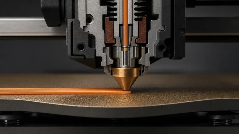
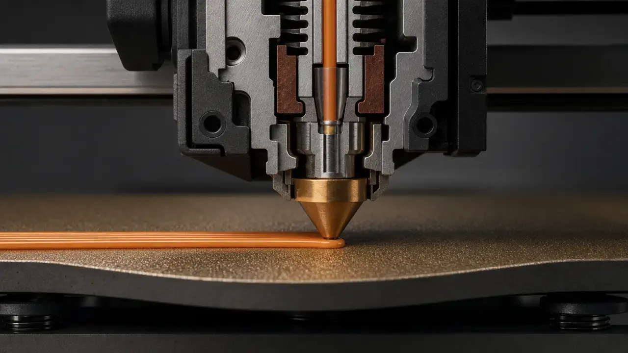
Bed adhesion in FDM/FFF material extrusion is the first layer’s ability to stay attached during printing and then release safely afterward. When first layer adhesion fails, the usual symptoms are familiar: a 3D print not sticking to the bed, corners lifting, lines separating, or the whole part shifting. [8]
The fastest workflow is usually not “lower Z until it works.” Start by confirming the correct plate and profile, cleaning the build surface with a compatible method, and making sure leveling or mesh compensation actually ran. Then fine-tune Z-offset and temperatures, and only after that use slicer helpers such as brims or rafts. It also helps to frame failure in two directions: under-adhesion, where the part lifts or moves, and over-adhesion, where removal becomes difficult or the sheet can be damaged. For terminology, ISO/ASTM 52900:2021 is Edition 2, published in November 2021 and confirmed in 2025, and “FDM/FFF” remains practical wording because FDM is a registered Stratasys trademark. [1] [7] [8] [11] [16]
3D print not sticking to the bed
When a 3D print is not sticking to the bed, the problem usually appears within the first minutes: lines do not join, the bead looks round instead of pressed into the surface, corners start to curl, or the part breaks loose and shifts. The opposite failure matters too. Some material and surface combinations grip so strongly that removal becomes risky, especially PETG on smooth PEI. Prusa’s first-layer guidance captures the right approach: clean first, use the correct sheet and material combination, and treat glue as either an adhesion aid or a protective separation layer depending on the interface. [7] [8]
| Symptom | Likely cause | First check |
|---|---|---|
| Lines not joining or visible gaps | Z-offset/live Z too high or under-extrusion | Run a first-layer test and check live Z before changing other settings. [8] |
| Corners lifting | Shrinkage stress, strong cooling, or drafts | Reduce drafts; for ABS/ASA, consider an enclosure. [12] [24] |
| Entire part shifts | Weak initial grip or leveling/mesh problem | Verify bed leveling or mesh compensation actually ran. [11] |
| First layer looks flat but still releases | Contamination, wrong plate profile, or too-cold bed | Re-clean the surface and verify plate type and temperatures. [8] |
| Sticks too well or risks sheet damage | Incompatible material and surface pairing | Use glue as a separation layer or switch plates. [7] [8] |
| Good-looking squish but still releases | Real nozzle gap differs from the commanded setup | Check sheet state, probe behavior, and Z-offset together. [10] [11] |
| Sheet damage risk during removal | Over-adhesion, especially with aggressive materials | Follow the plate maker’s removal guidance and let the plate cool first. [7] [14] [15] |
Before making aggressive changes, debug the interface in order: plate choice, cleanliness, material profile, leveling or mesh, then Z-offset. Marlin’s bed-leveling documentation is explicit that mesh compensation changes nozzle height over the surface so the nozzle follows bed contours; it does not mechanically flatten the bed. [8] [11]
- Confirm the correct plate type and profile in the slicer or printer. [8]
- Clean the surface using a compatible method for that plate. [8] [14] [15]
- Verify leveling or mesh compensation ran successfully. [11]
- Adjust Z-offset/live Z minimally, based on a first-layer test pattern. [8] [10]
- Slow the first layer if dragging, tearing, or poor wetting persists. [8]
- Adjust bed and nozzle temperatures within manufacturer ranges for that material and plate. [6] [7] [14] [15]
- Add a brim or raft only after the interface is correct. [9] [22]
Bed adhesion workflow: what to check first and why
A useful troubleshooting order is profile first, surface second, leveling or mesh third, and Z-offset fourth. That matches how the machine builds the first layer. If the wrong plate type or filament profile is loaded, the printer can use the wrong temperatures or assumptions. If the sheet is contaminated, even a well-calibrated first layer can fail. If mesh compensation is wrong or missing, the printer may be correct in one area of the bed and wrong somewhere else. Only after those are stable does Z-offset become the right fine-tuning tool. [8] [11]
Do not use a lower and lower Z-offset as a shortcut. Prusa explicitly warns against compensating for poor adhesion by over-squishing the first layer, because that can damage the sheet and hide the real fault. A dirty plate, the wrong material and plate pairing, or a failed mesh routine can all masquerade as “needs more squish.” The safer approach is to fix one interface variable at a time, test again, and only then move to the next. [8] [10]
First layer adhesion settings
Bed leveling, mesh leveling, and Z-offset solve different problems. Bed leveling or tramming makes the nozzle path more consistent relative to the bed plane. Mesh leveling then measures local variation and compensates for it during motion. Marlin describes this as the nozzle following bed contours by dynamically adjusting Z position. Z-offset comes after that and shifts the overall first-layer gap up or down. These are related settings, but they are not interchangeable. [10] [11]
Commanded first-layer height is not the same as the actual nozzle gap. The real squish depends on probe behavior, sheet thickness, temperature state, and surface texture, which is why a slicer value that looks sensible can still print too high, too low, or inconsistently across the bed. Prusa’s mesh bed leveling page gives a concrete example: with magnet compensation on older PINDA/SuperPINDA-based systems, some points can read off by as much as 80 μm near magnets. Prusa’s first-layer troubleshooting also treats “too close” and “too far” as distinct failure modes rather than one generic calibration issue. [8] [10]
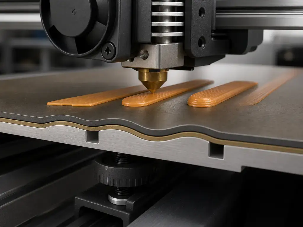
First-layer speed, extrusion width, and flow rate are best understood as contact-area and wetting-time levers, not magic percentages. Slower movement gives the hot filament more time to wet the surface. A wider first-layer bead can increase the real contact area. Flow changes how fully the extrudate fills the available gap. That is why a first layer can look acceptable and still peel up later, or why an overfed first layer can smear and drag even though the nozzle seems low enough. It is an interface problem, not a single-number problem. [4] [8]
Build surfaces & adhesion aids
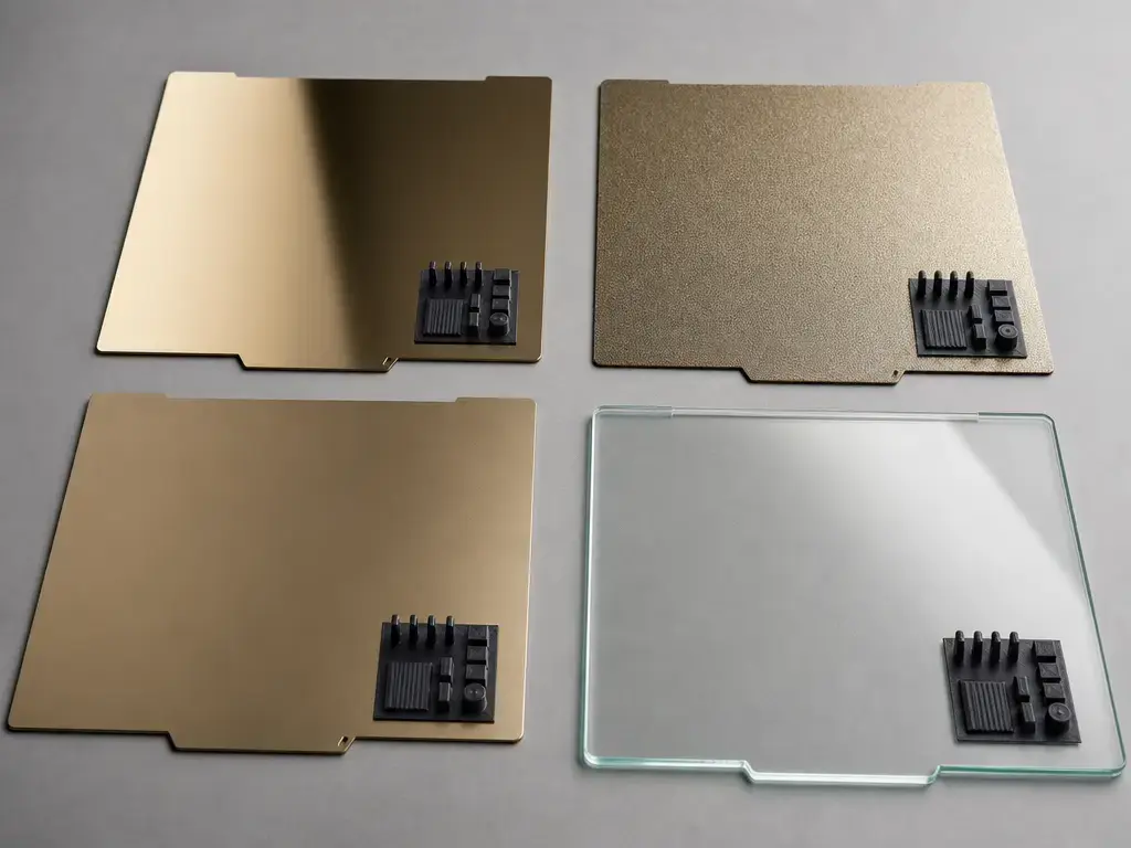
This section covers smooth, textured, and satin PEI-coated spring steel, plus glass; always follow your plate maker’s solvent and removal guidance for other coatings. [8] [14] [15]
| Surface | What it’s good at | Common failure mode | Safety/maintenance note |
|---|---|---|---|
| Smooth PEI | Strong adhesion and a smooth underside finish on many common filaments | PETG and other aggressive materials can over-bond | Prusa warns PETG on smooth PEI might damage the sheet; use glue as a separation layer if you print it there. [7] [8] |
| Textured PEI | Easier release after cooling and a durable textured finish | Small-footprint parts or some materials may still need temperature or interface tuning | Bambu says not to clean textured PEI with acetone and recommends regular detergent-and-water cleaning. [14] |
| Satin PEI | Middle-ground behavior between smooth and textured | Wrong cleaning method or wrong material assumptions for the finish | Prusa treats satin as its own surface and says never to use acetone on it. [8] |
| Glass | Flat, rigid surface that can work well when clean and correctly prepared | Adhesion depends heavily on cleanliness and any coating or helper layer in use | UltiMaker uses glass as a build-surface example and notes that dirt or grease undermines adhesion. [20] |
Two adhesive roles should be kept separate:
-
Adhesion promotion. Glue or similar interface layers can increase wetting and stabilize the first layer on difficult surfaces or materials. Hirsch et al. reported surface-energy changes from 13.99 mN/m on unmodified FR-4 to 63.16 mN/m with the tested PVA adhesive, which helps explain why adhesives can change bed behavior rather than merely add stickiness. These values come from controlled tests with specific materials, surfaces, adhesives, and methods, and are not universal printer presets. [4] [8]
-
Release or sacrificial layer. The same glue layer can also reduce over-adhesion and protect the sheet. The best-known example in the cited manufacturer guidance is PETG on smooth PEI: PETG can bond too strongly, and glue is recommended as a separation layer if smooth PEI is used anyway. [7] [8]
Cleaning is surface-specific. Prusa recommends 90%+ IPA for routine degreasing on its steel sheets, but says textured and satin sheets should never be cleaned with acetone. It also warns that smooth PEI plus PETG plus IPA can make the print adhere extremely strongly. Bambu’s PEI plate pages likewise warn against acetone and recommend regular detergent-and-water cleaning. In practice, contamination changes bed adhesion more than many slicer tweaks do. [8] [14] [15]
Research substrates are useful for explaining mechanisms, but they are not the same as a consumer spring-steel plate. Hirsch et al. used FR-4-backed setups and tested PVA, PVP, and PEI-related interfaces under controlled conditions. That helps explain wetting, surface energy, and release behavior, but lab numbers from those rigs do not translate directly into a single best plate for every desktop printer. [4]
Material-specific bed adhesion
PLA and PETG often fail in different ways. With PLA, the common complaint is weak first-layer bonding at corners or on small contact patches. Prusa lists PLA example ranges of 185–235 °C nozzle and 50–60 °C bed, which are useful as profile context rather than universal targets. With PETG, the problem is often the opposite: strong hold during printing and difficult removal afterward. Prusa’s PETG page lists 230 °C for the first layer and 240 °C for later layers, with 85 °C and 90 °C for the bed, and explicitly warns against smooth PEI unless a glue separation layer is used. [6] [7]
ABS, ASA, and nylon make the thermal side of bed adhesion more obvious. Prusa’s enclosure guide explains that higher-temperature filaments can cool too fast, shrink, and pull the lower layers upward even when the first layer started correctly. That is why an enclosure might be needed for ABS, ASA, PC, PA, PP, and related composites. Prusa’s layer-separation guide is even more direct for ABS: cold air can trigger failure, and ABS is best printed in an enclosed chamber. For nylon, moisture adds another variable. Prusa says improper storage can let nylon absorb water up to 10% of filament weight, and Hirsch et al. pre-dried ABS, PETG, and PA12 at 70 °C before printing in their adhesion study. [12] [13] [24] [4]
TPU and other flexibles are usually less about brute-force grip than about controlled release and predictable handling. Prusa recommends glue for FLEX in its smooth PEI workflow, while Bambu’s plate guidance shows TPU settings around 35–45 °C and uses glue on some smooth-PEI and filament-specific TPU combinations. That is a reminder that “use glue” is often interface guidance tied to a specific surface and material pairing, not a universal rule for all flexible filaments. [8] [14] [15]
- PLA: If it peels early, check first-layer gap, surface contamination, and whether the bed is within the material’s normal profile range. [6] [8]
- PETG: Watch for over-adhesion on smooth PEI and use a separation layer where the manufacturer recommends it. [7] [8]
- ABS/ASA: Treat drafts and enclosure conditions as part of bed-adhesion control, not just a later print-quality issue. [12] [24]
- PA/nylon: Moisture handling matters before the first layer starts, not only after surface defects appear. [13] [4]
- TPU/flexibles: Plate-specific glue guidance may be about safe release and surface protection as much as adhesion. [8] [14] [15]
Manufacturer examples (not universal rules)
Prusa and Bambu are offering different kinds of guidance, not necessarily conflicting guidance. Prusa’s material pages are mostly material-centered examples, while Bambu’s plate pages tie temperatures and glue use to specific surfaces. Read both as manufacturer-specific starting points rather than universal rules. [6] [7] [14] [15]
Slicer adhesion helpers
- Skirt: Primes and stabilizes flow before the model starts; it does not increase the model’s contact area with the bed. [9]
- Brim: Adds first-layer area around the part, which helps small bases and tall parts resist lifting. Prusa advises at least a 3 mm brim when a brim is needed. [9]
- Raft: A sacrificial foundation under the part that can mask a difficult interface, but it adds time and usually worsens the bottom-surface finish. MakerBot’s Z18 manual describes a raft as a base printed on the build plate for the object. [22]
Use these after the interface is already correct, not instead of correcting it. UltiMaker calls a brim a common adhesion method, which is fair, but even a well-designed brim is still a trade-off: more material, more cleanup, and a larger footprint around the model. A raft is more forgiving than a brim, but it moves the print onto a secondary base and can cost surface quality underneath. [21] [22]
Why the first layer sticks
Bed adhesion is the bond between the extruded polymer and the build surface. Interlayer adhesion is different: it is the bonding between roads and layers inside the printed part, driven mainly by polymer diffusion and entanglement after extrusion. Keeping those separate matters because a print can have decent internal bonding and still fail at the bed, or the reverse. At the bed, the main variables are wetting, real contact area, cleanliness, surface chemistry, and whether cooling and shrinkage forces are restrained long enough for the first layer to stay put. [3] [4]
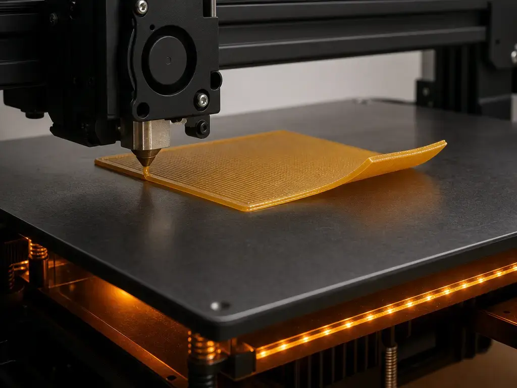
Cleanliness and surface chemistry change what the polymer actually meets at the interface. Hirsch et al. reported a surface-energy increase from 13.99 mN/m to 63.16 mN/m with the tested adhesives, and the highest interfacial shear strength in that study reached 7.3 MPa for PA12 with PVA adhesive. Those numbers are useful because they show that the same polymer can behave differently when the interface changes. These values come from controlled tests with specific material, surface, adhesive, geometry, and method, and are not universal printer presets. [4]
A heated bed helps because it slows cooling and reduces warping stress at the interface. NIST’s engineering description says FDM machines often extrude onto a heated plate to reduce warping and improve filament adhesion. In the same report, a heated-bed warm-up example starts from a 293 K environment and models the bed reaching 373 K to operate. That 293 K-to-373 K figure is an example model, not a recommended bed temperature. Hotter is not automatically better; the useful range still depends on material, surface, and geometry. [3]
Metrics & what can actually be measured
What users can observe is straightforward: whether the print sticks, lifts at an edge, shifts, or releases safely. What labs can measure is more formal: surface energy, interfacial shear strength, removal force, and warpage-related displacement under controlled conditions. ASTM’s additive manufacturing standards list shows that material-extrusion standards exist, including ISO/ASTM 52903-1-20 and ISO/ASTM 52903-2-20, but that is not the same as a universal consumer bed-adhesion tolerance number. [2]
Hirsch et al. used laboratory metrics such as surface energy and interfacial shear strength to compare interface conditions, while Snapp et al. studied removal force versus bed temperature in a specific PLA setup on bare borosilicate glass and polyimide-coated beds. In that tested setup, Snapp reported bed adhesion maximized between 60 and 70 °C, and cooling below 40 °C gave minimal additional removal benefit. These values come from controlled tests with specific material, surface, adhesive, geometry, and method, and are not universal printer presets. [4] [5]
The practical conclusion is simple: no universal consumer bed-adhesion specification or number was found. The Aalto thesis record explicitly notes a lack of standardized solution and method for 3D-printer adhesion testing, which fits the gap between lab metrics and everyday printer troubleshooting. [23] [2]
Controlled adhesion has always mattered
Primary sources show that “stick enough, then release safely” is not a new concern. U.S. Patent 5,939,008 describes flexible sheet substrates, notes layers that are weakly adhered for removal, and describes flexing the substrate to peel it away from the part. It also discusses substrate concepts such as sand-coated or sandpaper-style surfaces attached by tape. That is evidence that removable, controlled adhesion was designed into early extrusion-style systems rather than treated as an afterthought. [19]
Later sources keep the same logic. US6722872B1 describes building objects in a heated chamber onto a base or substrate, and Stratasys’ FDM process overview mentions inserting a base, closing the chamber door, and heating the build chamber. UltiMaker’s educational material gives the consumer-scale version of the same idea: blue tape and glass are surface examples, and dirt or grease will undermine adhesion. [17] [18] [20]
Common mistakes + safe removal
The most common mistake is chasing bed adhesion by endlessly lowering Z-offset. That can hide contamination, a wrong plate and material pairing, or failed mesh compensation while increasing the risk of nozzle drag and sheet damage. Another is ignoring plate compatibility. Prusa warns that PETG on smooth PEI can damage the sheet and that glue can serve as a protective separation layer there. It also warns that IPA on a smooth sheet immediately before PETG can make the bond extremely strong and removal difficult. [7] [8] [10]
Removal should be treated as part of first-layer planning, not as an afterthought. Bambu uses 35 °C or lower as a PEI-plate removal example on its plate pages, but that is manufacturer guidance, not a universal threshold for every plate on the market. The broader rule is to let the interface relax and release instead of forcing a part off while the bond is still strongest. [14] [15]
Key takeaways
Reliable bed adhesion usually comes from sequence, not guesswork: clean the plate, load the correct profile, confirm mesh or manual leveling, fine-tune Z-offset, verify temperatures, and use brim or raft only last. That order solves the most common first-layer failures without masking the root cause. It also reduces the opposite problem, over-adhesion, where the print succeeds but the plate suffers. Glue can be an adhesion aid, a separation layer, or both, depending on the material and surface. [8] [9] [11]
FAQ
What is bed adhesion in FDM/FFF 3D printing?
Bed adhesion is the attachment between the first deposited layer and the build surface during material-extrusion printing. In practical terms, it means the print stays fixed while the part is built, then releases without damaging the surface or the part. That makes bed adhesion different from interlayer adhesion, which is the bonding between roads and layers inside the print itself. [3] [4]
Why is my 3D print not sticking to the bed even after leveling?
Because leveling is only one part of the interface. A clean plate, the correct surface profile, appropriate temperatures, and a realistic Z-offset all matter too. Mesh leveling can compensate for bed shape, but it cannot fix contamination or a bad material and surface pairing. If leveling seems fine and the print still lifts, check plate type, cleaning method, and first-layer conditions next. [8] [10] [11]
What should I change first for first layer adhesion: cleaning, Z-offset, or bed temperature?
Start with cleaning and the correct profile, then confirm leveling or mesh, then adjust Z-offset, and only after that fine-tune temperatures. That order matters because a dirty surface or wrong plate profile can make Z-offset adjustments misleading. Temperature helps, but it is usually not the first thing to change if the underlying interface is contaminated or misconfigured. [6] [7] [8] [11]
Why does the first layer look “squished” but still not stick?
Because visible bead shape is not the whole story. Commanded first-layer height is not the same as the real nozzle gap, and apparent squish can be affected by probe behavior, sheet thickness, temperature state, and surface texture. A line can look flattened and still release if the surface is contaminated, the plate type is wrong, or the interface chemistry is unstable for that material. [8] [10]
Why can PETG damage a smooth PEI sheet, and when is glue a release layer?
PETG can bond so strongly to smooth PEI that removal risks tearing or damaging the sheet. In that situation, glue is not mainly there to make the part stick more; it acts as a protective separation layer between the material and the surface. Prusa explicitly uses PETG on smooth PEI as a warning example for over-adhesion. [7] [8]
Expert: How does bed temperature influence warping stress vs adhesion at the interface?
A heated bed slows cooling at the base of the part, which reduces warping stress and gives the first layer more time to maintain contact. NIST describes heated plates in exactly that engineering context. In Snapp’s tested PLA setup, adhesion peaked between 60 and 70 °C, and cooling below 40 °C gave little extra removal benefit. Those numbers are test-specific, not universal presets for every plate and polymer. [3] [5]
Expert: What do lab metrics like surface energy and interfacial shear strength actually measure in bed-adhesion studies?
They measure parts of the interface that users can only infer indirectly. Surface energy relates to wetting behavior and contact compatibility, while interfacial shear strength measures how strongly the printed part resists sliding failure at the interface under a specific test setup. Hirsch et al. reported a surface-energy change from 13.99 to 63.16 mN/m and a highest interfacial shear strength of 7.3 MPa in their tested system. Those are controlled-study metrics, not consumer target values. [4]
Related on 3D Mag
Sources
- ISO — ISO/ASTM 52900:2021 standard page (Standard). https://www.iso.org/standard/74514.html?browse=tc. Accessed 2026-07-26.
- ASTM — Additive Manufacturing Standards list (Standards register). https://store.astm.org/products-services/standards-and-publications/standards/additive-manufacturing-standards.html. Accessed 2026-07-26.
- NIST — NIST IR 8490 PDF (Official report). https://nvlpubs.nist.gov/nistpubs/ir/2023/NIST.IR.8490.pdf. Accessed 2026-07-26.
- Hirsch et al. — Fraunhofer open-access PDF on print bed adhesion (Scientific). https://publica-rest.fraunhofer.de/server/api/core/bitstreams/fbc6f55a-b407-4ef5-963a-3bda55299dfb/content. Accessed 2026-07-26.
- Snapp et al. — NSF PAR record on bed temperature modulation (Scientific record). https://par.nsf.gov/biblio/10291472-increasing-throughput-fused-deposition-modeling-modulating-bed-temperature. Accessed 2026-07-26.
- Prusa — Filament Material Guide (Manufacturer documentation). https://help.prusa3d.com/filament-material-guide. Accessed 2026-07-26.
- Prusa — PETG material page (Manufacturer documentation). https://help.prusa3d.com/article/petg_2059?product=mk4s. Accessed 2026-07-26.
- Prusa — First layer issues (Manufacturer documentation). https://help.prusa3d.com/article/first-layer-issues_1804?product=mk3-5s. Accessed 2026-07-26.
- Prusa — Skirt and Brim (Software documentation). https://help.prusa3d.com/article/skirt-and-brim_133969. Accessed 2026-07-26.
- Prusa — Mesh bed leveling (Manufacturer documentation). https://help.prusa3d.com/article/mesh-bed-leveling_112163. Accessed 2026-07-26.
- Marlin — G29 Bed Leveling docs (Firmware documentation). https://marlinfw.org/docs/gcode/G029.html. Accessed 2026-07-26.
- Prusa — Enclosure guidepost (Manufacturer documentation). https://help.prusa3d.com/article/enclosure-guidepost_366332?product=enclosure. Accessed 2026-07-26.
- Prusa — Polyamide (Nylon) page (Manufacturer documentation). https://help.prusa3d.com/article/polyamide-nylon_167188?product=mk3s. Accessed 2026-07-26.
- Bambu Lab — Textured PEI Plate page (Manufacturer documentation/store). https://us.store.bambulab.com/en/products/bambu-textured-pei-plate. Accessed 2026-07-26.
- Bambu Lab — Build plate page with Smooth PEI guidance (Manufacturer documentation/store). https://jp.store.bambulab.com/en/products/bambu-build-plate. Accessed 2026-07-26.
- Stratasys — Legal & Terms page (Manufacturer legal). https://www.stratasys.com/en/stratasysdirect/about-us/legal-terms/. Accessed 2026-07-26.
- Stratasys — “3D Printing with FDM” white paper PDF (Manufacturer white paper). https://www.stratasys.com/contentassets/ab0627bfea864302a7d732278e04ad12/wp_fdm_3dprintingwithfdm_0818a.pdf?v=4a0525. Accessed 2026-07-26.
- Patent — US6722872B1 High temperature modeling apparatus (Patent). https://patents.google.com/patent/US6722872B1/en. Accessed 2026-07-26.
- Patent — U.S. Patent 5,939,008 “Rapid prototyping apparatus” (Patent). https://patents.justia.com/patent/5939008. Accessed 2026-07-26.
- UltiMaker — “Ultimaker Schooling – 3D printing” (Manufacturer educational content). https://ultimaker.com/learn/ultimaker-schooling-3d-printing/. Accessed 2026-07-26.
- UltiMaker — “Important 3D printing software features” PDF (Manufacturer white paper). https://ultimaker.com/wp-content/uploads/2024/06/important-3d-printing-software-features.pdf. Accessed 2026-07-26.
- MakerBot — Replicator Z18 User Manual PDF (Manufacturer manual). https://um-support-files.ultimaker.com/manuals/user-manual/Replicator/Z18%20-%20User%20manual%20-%20EN.pdf. Accessed 2026-07-26.
- Aalto University — Thesis record “Bed adhesion in extrusion 3D printing process” (Academic thesis record). https://aaltodoc.aalto.fi/items/b6ae2fbc-b84d-47a4-beb7-0b4bc20a70c3. Accessed 2026-07-26.
- Prusa — “Layer separation and splitting FDM” (Manufacturer documentation). https://help.prusa3d.com/article/layer-separation-and-splitting-fdm_1806. Accessed 2026-07-26.