
Summary
3D printing wall thickness affects whether a part can be sliced cleanly, handled after printing, and used with the needed balance of strength, surface quality, time, and material use. In additive manufacturing, parts are built as physical 3D geometries by successive addition of material, but the wall that works in one process or printer setup may fail in another. [1]
There is no universal best or minimum wall thickness. ISO/ASTM 52902 is a geometric capability assessment standard, but it does not prescribe one manufacturing procedure or one set of machine settings for a test piece, so it cannot be read as a universal wall-thickness rule. [2] In practice, a workable wall depends on the process, material, part size, orientation, wall height, local support condition, slicer behavior, and what happens after printing, such as washing, post-curing, unpacking, depowdering, machining, or sanding. [2]
What is wall thickness in 3D printing?
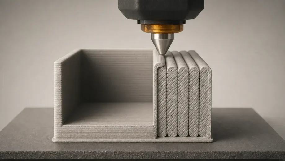
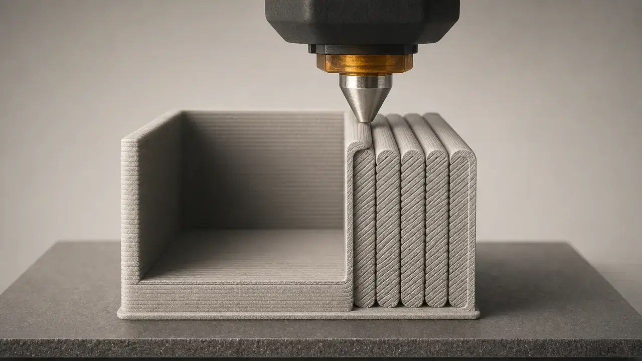
Wall thickness is the distance between one surface of a part and the opposite surface across that wall section. In a hollow box, it is the shell thickness from the outside face to the inside face. In a solid rib or blade-like feature, it is the width of that feature through its thinnest cross-section. [18]
In practice, three meanings get mixed together. The first is CAD nominal wall thickness, which is what you modeled. The second is slicer-target shell thickness, which is what the slicer tries to create from perimeter count, line width, and related settings. The third is as-printed wall thickness, which is what the finished part actually measures after toolpath generation, material flow, shrinkage, curing, cooling, and post-processing. [4] [10] A mesh adds another complication: Autodesk’s Fusion documentation notes that a mesh has no thickness by itself, so manufacturable thickness comes from how the geometry encloses volume, not from a surface display alone. [4]
Wall thickness is not the same as strength, accuracy, or resolution. It often affects those outcomes, but it remains its own geometric variable. Infill is separate again: UltiMaker’s software guide treats 0% infill as a completely hollow model and 100% infill as a completely solid one, which shows that internal fill percentage and wall geometry are different controls. [8]
Do not confuse wall thickness with:
- layer height. [6]
- line width or extrusion width. [9]
- infill density. [8]
- top or bottom thickness. [6]
- dimensional tolerance. [18]
- surface texture settings such as fuzzy skin. [7]
Why wall thickness rules exist
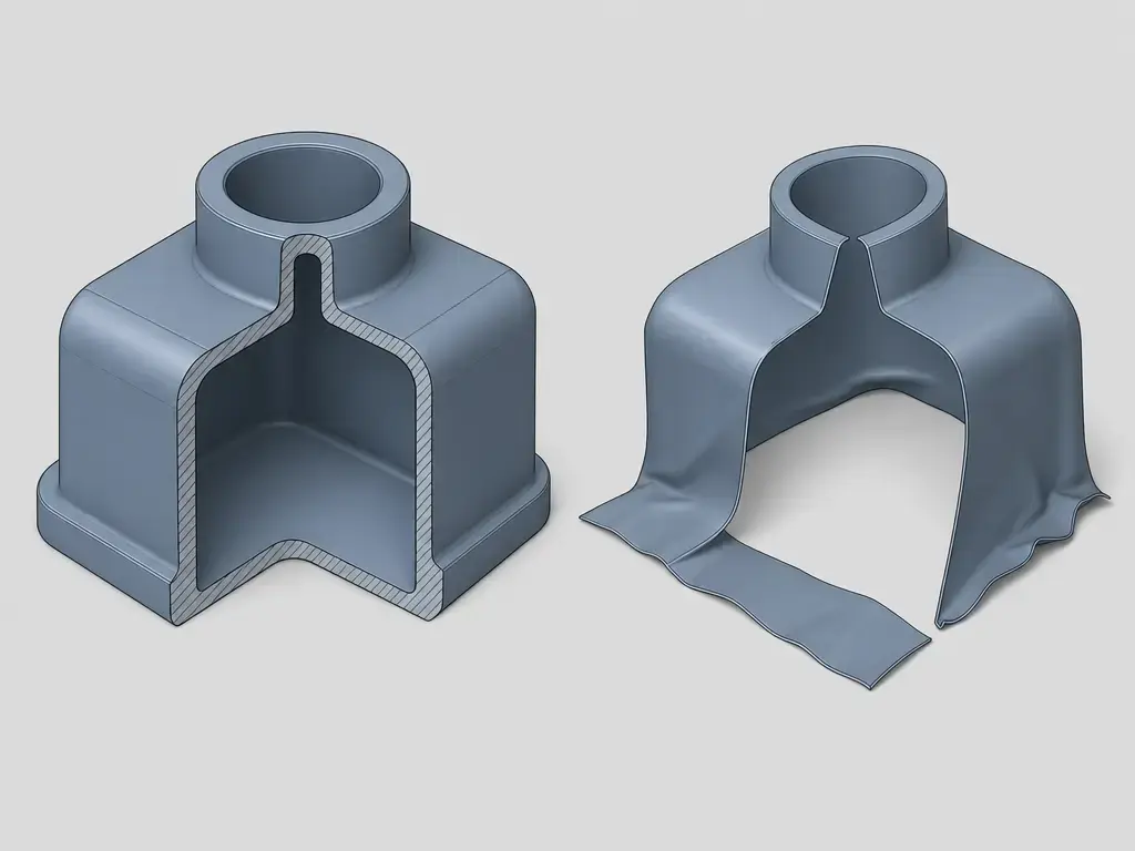
Slicers need valid, closed geometry. Blender’s 3D Print Toolbox describes printable meshes as watertight closed surfaces, defines non-manifold edges as edges that do not connect to exactly two faces, and warns that very thin geometry may be missed entirely by the slicer. [3] Autodesk adds the complementary point that a mesh itself has no thickness. [4] Together, those points explain why a part can look plausible on screen and still fail as printable geometry if the shell is non-manifold, open, or effectively zero-thickness. If a model is non-manifold or a wall collapses into a surface without enclosed volume, walls and fine features can disappear in preview or in the printed part. [3] [4]
Perimeters vs wall thickness
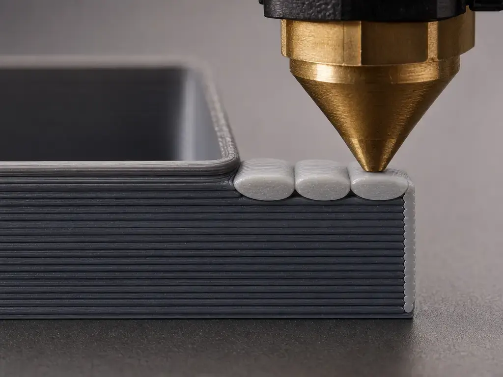
In FDM and FFF slicers, perimeters, walls, wall loops, and wall line count describe how many extrusion paths are placed around the outside of each layer. They are path-count terms, not direct measurements of the finished wall. A slicer may be told to print two or three wall loops, but the real wall thickness still depends on the line width used for those loops and on whether the slicer keeps widths fixed or varies them. [9] [10]
A useful profile-specific example comes from Prusa. In its modeling guide, Prusa uses a 0.4 mm nozzle and a PrusaSlicer extrusion width of 0.45 mm, giving about 0.45 mm for 1 perimeter, 0.9 mm for 2, 1.35 mm for 3, and 1.8 mm for 4. Prusa also states that walls thinner than one nozzle perimeter are not printable. [5] That is helpful beginner math, but it is not a universal FDM law. It is a slicer-profile example, and Prusa explicitly labels those numbers as approximations that may vary with slicer settings. [5] The important distinction is that nozzle diameter and actual line width are related but not identical, so “0.4 mm nozzle” does not automatically mean “0.4 mm printed wall line.” [5] [9]
Simple FDM/FFF wall formula
For beginners, the simplest estimate is: approximate wall thickness = wall line count × line width. [5] This is a good first pass for turning a CAD wall into slicer settings, especially when you want a shell that lands close to one, two, three, or four perimeter paths. But it is only a starting estimate, not a measurement guarantee. [5] [10]
Why the math is approximate
The approximation breaks down because slicers do not always keep every wall line at one fixed width. OrcaSlicer’s documentation says the Classic wall generator uses the defined line width and does not vary extrusion width, while Arachne dynamically adjusts extrusion width to follow thin features and wall-count transitions more closely. [10] OrcaSlicer’s line-width guide also notes that Arachne uses configured widths as a reference rather than a strict constant. [9] That behavior matches adaptive-width toolpath research, which aims to reduce underfill and overfill in contour-parallel paths. [24] Use the formula to plan, then verify the real toolpaths in slicer preview or by measurement on a test print. [10]
Wall thickness vs infill
Walls and infill do different jobs. The wall defines the outer shell, visible shape, edge stiffness, and much of the part’s local durability. Infill fills the interior and changes mass, print time, support for top surfaces, and some mechanical behavior. UltiMaker’s guide makes the endpoints clear: 0% infill is completely hollow, while 100% infill is completely solid. [8] A part can therefore have thick walls with light infill, thin walls with dense infill, or any mix in between.
The strength tradeoff is real, but it is not universal. In one PLA study using a Creality Ender 3 V2, Ultimaker Cura, 20% infill, and 0.20 mm layer height, the measured Young’s modulus for 1, 2, and 3 perimeters was 626.14 MPa, 719.99 MPa, and 804.29 MPa. [22] That does show a stiffness increase with perimeter count in that setup, but it should not be generalized across all materials, printers, or load cases. [22] Do not claim that walls are always better than infill unless you are describing a specific test configuration and response metric. [22]
When to increase wall thickness before infill:
- thin boxes, brackets, clips, or enclosures that see bending loads
- screw bosses, inserts, corners, and edges that load the shell directly
- parts that need sanding or other post-processing allowance
- hollow resin or powder-bed parts that need more handling strength after printing. [13] [15] [21]
Shell thickness, top and bottom thickness, and hollow parts
In slicer language, shell thickness usually means the side walls built by perimeters, while top and bottom thickness refers to horizontal solid skins. Prusa’s documentation shows why “top thickness = number of solid layers × layer height” is only an approximation tied to a profile: to keep a similar top or bottom thickness, a 0.3 mm layer height can use 3 top layers, while a 0.1 mm layer height can use 9. [6] The logic is useful, but local layer height, profile defaults, and variable-layer-height features can all change the result. [6]
Hollow parts add another reality check. In resin, polymer powder-bed, and metal workflows, a wall must survive washing, post-cure, unpacking, depowdering, and handling, not just the moment of printing. Fuse 1 documentation warns that unsupported walls at or below 0.6 mm may warp or detach, and a SAF powder-bed design guide notes that very small features may not survive unpacking and depowdering even if they can be built. [15] [21]
Minimum wall thickness by process
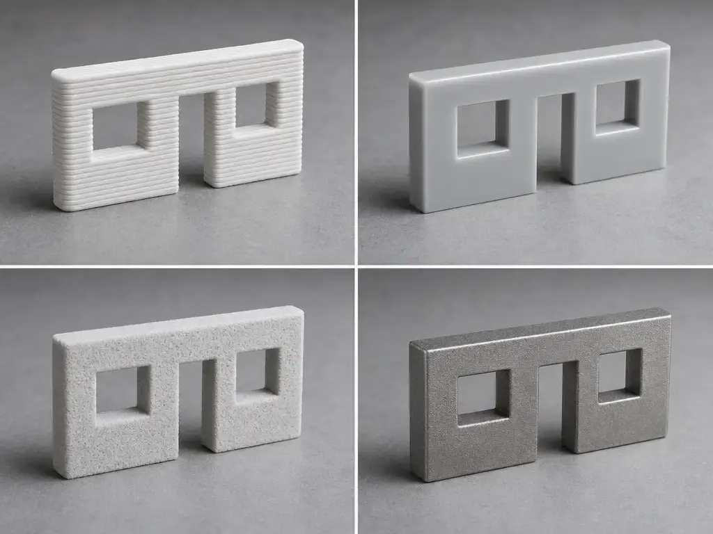
Treat the values below as source-specific starting points, not guarantees. Different processes create and support walls in different ways: FDM extrudes a bead, resin processes must resist peel and solvent handling, polymer powder-bed parts are supported by surrounding powder but still need post-processing survivability, and metal powder-bed walls are tied to heat flow, support strategy, and residual stress. [5] [13] [14] [18]
| Process | Source-specific minimum example | Best use in article | Caveat |
|---|---|---|---|
| FDM/FFF (material extrusion) | Prusa example: 0.4 mm nozzle, 0.45 mm line width, 1 perimeter ≈ 0.45 mm. [5] | Explain slicer math and geometric printability | Profile-specific; wall generator and line width change the outcome |
| Vat photopolymerization (SLA/resin) | Formlabs Form 4/Form 4B with Grey Resin V5 at 50 µm: intended minimum supported wall 0.2 mm, actual 0.17 mm; intended minimum unsupported wall 0.2 mm, actual 0.18 mm. [13] | Show a high-resolution resin example | Not a universal SLA, DLP, or MSLA guarantee; wash and post-cure still matter |
| Polymer powder bed fusion (SLS example) | Formlabs Fuse 1 generation with Nylon 12: vertical walls 0.6 mm, horizontal walls 0.3 mm for both supported and unsupported cases. [14] | Show powder-process wall rules | Handling and depowdering can still damage thin parts |
| Metal powder bed fusion (LPBF/DMLS example) | Materialise AlSi10Mg: 1.0 mm Standard Grade, 0.5 mm Performance Grade, and 2.0 mm recommended for structural walls. [18] | Show metal-specific DfAM constraints | Alloy-, provider-, and process-specific; thickness alone is not enough |
“Supported” and “unsupported” are process-specific labels, not one universal condition. In FFF they relate to bead placement and shell generation, in vat photopolymerization to local connectivity and peel and handling risk, in polymer powder-bed fusion to geometry plus post-depowdering survivability, and in metal powder-bed fusion to thermal and mechanical support conditions. [10] [13] [14] [19]
- FDM/FFF: the Prusa number above is a path-planning example tied to a 0.4 mm nozzle and 0.45 mm extrusion width, not a service-bureau acceptance rule. [5]
- Resin: the 0.2 mm figures apply to Form 4/Form 4B, Grey Resin V5, and 50 µm layer height. [13]
- Polymer powder bed: the Fuse 1 values come from Nylon 12 on that platform; thin walls may still warp, detach, or be damaged during powder removal and handling. [14] [15]
- Metal powder bed: the Materialise values are for AlSi10Mg guidance, and thicker zones can also increase stress and deformation risk. [18]
FDM and FFF minimums: three different meanings of minimum
FDM discussions often mix three different “minimums” into one number, which creates unnecessary contradictions. Desktop slicer math answers whether a wall can be generated or printed at all, while service-provider rules answer whether it will meet stability and quality expectations in a qualified process. [5] [16] [17]
- Geometric printability floor: in the Prusa example, walls thinner than one perimeter are not printable, and one perimeter is about 0.45 mm with a 0.4 mm nozzle and 0.45 mm extrusion width. [5]
- Desktop starting points: Formlabs presents FDM 1 mm as a cross-process starting value and notes that with a 0.4 mm nozzle, 1.2 mm may print better than 1.0 mm because the thickness is divisible by 0.4. [12]
- Industrial or service-provider manufacturability rules: Stratasys Direct recommends a minimum FDM wall of 4× layer height, giving 0.028 in for a 0.007 in layer height example, while Xometry recommends about 0.047 to 0.06 in, or 1.2 to 1.5 mm, for supporting walls. [16] [17]
Resin and SLS wall minimums in context
For resin, keep the conditions attached to the number. In the Formlabs Form 4/Form 4B guide for Grey Resin V5 at 50 µm, supported means a wall connected to other walls on two or more sides, unsupported means connected on fewer than two sides, and both intended minimums are 0.2 mm, with actual printed values of 0.17 mm for supported walls and 0.18 mm for unsupported walls. [13] Here, “supported” and “unsupported” are resin-specific connectivity terms tied to peel forces and handling risk, not the same failure mode used in FFF or powder-bed rules. [13]
For SLS, Formlabs’ Fuse 1 generation guidance for Nylon 12 gives 0.6 mm for vertical walls and 0.3 mm for horizontal walls in both supported and unsupported cases, while defining unsupported walls as connected on fewer than two sides. [14] That sounds permissive, but powder-bed survivability is still part of the rule. The Fuse 1 user guide warns that unsupported walls of 0.6 mm or less may warp or detach and that thinner walls have reduced strength, and Stratasys’ SAF guide independently warns that very small features may not survive unpacking and depowdering. [15] [21]
Metal powder bed fusion wall thickness: height, stress, and support strategy
Metal powder bed fusion examples show why thickness alone is not enough. Materialise’s AlSi10Mg guidance lists 1 mm minimum walls for Standard Grade, 0.5 mm for Performance Grade, recommends 2 mm for structural walls, and warns that thicker areas can increase stresses enough to cause deformation or unstable builds. [18] Protolabs adds that thin walls below 0.040 in, or 1 mm, should keep a wall height-to-thickness ratio below 40:1, and that thick cross sections require more support structures to combat stress and prevent the part from pulling off the build plate. [19] A separate LPBF thin-wall study ties build failure and distortion to severe thermal distortion and residual stress during fabrication, with supports used to pin down open edges in overhang tests. [20] Read metal wall thickness together with wall height, support strategy, geometry, and heat flow. [18] [19] [20]
How to choose a good wall thickness for 3D printing
A good wall thickness is not the thinnest one that can sometimes print. It is the thinnest one that is printable, strong enough for the job, stable enough to manufacture, accurate enough for fit and finish, and economical in time and material. For FFF, UltiMaker’s basic printability rule is that wall thickness should be equal to or larger than the nozzle size being used. [8] For metal powder-bed parts below 1 mm, aspect ratio also enters the decision because the Protolabs rule flags walls under a 40:1 height-to-thickness ratio. [19]
A practical workflow is:
- Identify process and material. [12] [13] [14] [18]
- Find the manufacturer or service minimums for that exact setup. [12] [13] [14] [18]
- For FDM, convert the target wall into perimeters and line width, then preview the real toolpaths instead of trusting CAD thickness alone. [5] [10]
- Check unsupported spans and wall height or aspect ratio, especially in resin and metal. [13] [19]
- Add ribs or fillets instead of thickening every wall. [18] [19]
- Print a small coupon before committing to the final part. [5]
Small coupons matter because the slicer, orientation, and post-processing steps can change the final result. For regulated or safety-critical applications, validation, testing, and qualification are still required. [13] [19]
Performance metrics affected by wall thickness
Wall thickness can change printability, stiffness, static strength, impact behavior, leak resistance, dimensional accuracy, print time, mass, and cost. In some parts it mainly affects edge rigidity and handling; in others it determines whether the wall can be generated at all or whether it survives post-processing. [5] [11] [18]
The tradeoff is metric-dependent. In the PLA study cited earlier, increasing perimeter count from 1 to 3 at 20% infill and 0.20 mm layer height increased measured Young’s modulus from 626.14 MPa to 804.29 MPa in that specific setup. [22] But a 2026 PLA optimization study using layer heights of 0.05, 0.15, and 0.30 mm, infill densities of 10%, 40%, and 70%, and perimeter counts of 2, 4, and 6 reported about a 57% improvement in Grey Relational Grade while also showing conditions where impact strength decreased as perimeter count increased. [23] Improvements in one metric can degrade another. [23] Do not extrapolate these PLA-specific results to resin, SLS, or metal processes. [22] [23]
Applications where wall thickness decisions matter most
Wall-thickness choices matter most where the shell is doing real work or where post-processing removes margin. That includes snap-fit enclosures, hollow resin miniatures and display parts, FDM brackets, SLS ducting and housings, thin-rib metal parts, and parts that will be sanded, tapped, machined, or post-cured. In metal, a structural wall may call for something closer to the 2 mm recommendation seen in Materialise’s AlSi10Mg context, while in resin the often-quoted wall numbers only mean anything when the printer, resin, and layer height are stated together, such as Form 4/Form 4B with Grey Resin V5 at 50 µm. [18] [13]
- enclosures and snap-fits
- resin miniatures and hollow display parts
- FDM brackets and clips
- SLS ducting and housings
- metal manifolds and thin ribs
- parts to be sanded, tapped, machined, or post-cured
Limitations and common mistakes
Both thin and thick walls can fail, but for different reasons. Thin walls fail when the geometry is invalid, when the slicer cannot form a stable path, or when the part survives printing but not the handling that follows. Thick walls fail when they waste time and mass, distort other features, or create thermal stress problems in metal. [3] [5] [18]
Common thin-wall mistakes include modeling non-manifold or effectively zero-thickness geometry, assuming a wall below one line width can be rescued automatically, and confusing pin, wire, or detail minimums with wall-thickness limits. Blender warns that thin geometry can be missed entirely by the slicer, and Prusa states that walls thinner than one perimeter are not printable. [3] [5] In resin, even the close Form 4 measured values of 0.17 mm and 0.18 mm still depend on supported versus unsupported condition and the stated print setup. [13] In powder-bed polymer systems, survivability during unpacking and depowdering remains part of the real limit. [14] [21]
Over-thick walls are not automatically safer. In metal powder-bed work, Materialise warns that thicker areas can increase stress and deformation, while Protolabs notes that thick cross sections need more supports to manage stress and avoid pulling off the build plate. [18] [19] For regulated or safety-critical parts, validation, testing, and qualification are required. [19]
Practical takeaways for 3D printing wall thickness
The safest way to think about 3D printing wall thickness is as a process-specific design choice, not a single magic number. Use minimums as starting points, then verify what your geometry, slicer, and post-processing actually produce. [2] [5]
- Start from process-specific design guides. [12] [13] [14] [18]
- For FDM, design around line width and perimeter count, then verify in preview. [5] [10]
- For resin, always state supported versus unsupported plus printer, resin, and layer height when using numbers. [13]
- For powder processes, account for handling and depowdering, not just print formation. [15] [21]
- For metal PBF, consider aspect ratio, residual stress, and support strategy as well as thickness. [19] [20]
- Validate functional walls with test prints or coupons. [5]
FAQ
What is wall thickness in 3D printing?
Wall thickness in 3D printing is the distance across a part’s shell from one surface to the opposite surface. In practice, that is different from layer height, line width, infill percentage, or dimensional tolerance. [4] [8] It is also different from surface texture settings. Prusa describes fuzzy skin thickness as the maximum distance each skin point is offset perpendicular to the perimeter wall, which means fuzzy skin changes the exterior surface envelope rather than serving as structural shell thickness. [7] The useful habit is to ask whether you mean CAD wall thickness, slicer-target shell thickness, or the wall you actually measure on the printed part. [4]
Perimeters vs wall thickness: what’s the difference?
Perimeters are toolpaths; wall thickness is geometry. In a simple FDM estimate, approximate wall thickness equals wall line count times line width. [5] That is why Prusa’s 0.4 mm nozzle example with 0.45 mm extrusion width gives roughly 0.45 mm for one perimeter and 0.9 mm for two. [5] The caveat is that this is only approximate. OrcaSlicer’s Classic wall generator keeps a defined width, while Arachne can vary extrusion width to follow geometry more closely. [10] So perimeter count tells you how the slicer plans to build the shell, but not necessarily the exact final wall you will measure. [9] [10]
What is a good wall thickness for a 0.4 mm nozzle?
A good wall thickness for a 0.4 mm nozzle is conditional, not universal. Prusa’s example suggests about 0.45 mm for one perimeter, 0.9 mm for two, 1.35 mm for three, and 1.8 mm for four, with the warning that anything thinner than one perimeter is not printable. [5] Formlabs’ cross-process article gives 1 mm as an FDM starting point, but then adds that with a 0.4 mm nozzle, 1.2 mm may print better than 1.0 mm because the wall thickness is divisible by 0.4. [12] In practice, pick a target that matches your needed perimeter count and check the slicer preview. [5]
Wall thickness vs infill: which matters more for strength?
Neither always matters more. It depends on what “strength” means in the specific part and test. Walls strongly affect shell stiffness, edge durability, and the way forces enter the part, while infill changes interior support, mass, and some bulk behavior. [8] In the cited PLA test at 20% infill and 0.20 mm layer height, increasing perimeter count from 1 to 3 raised Young’s modulus from 626.14 MPa to 804.29 MPa. [22] But that is one printer-material-slicer setup, not a universal law. Also remember that 0% infill is hollow and 100% infill is solid, so the two controls are complementary rather than interchangeable. [8]
What is a good resin printing minimum wall thickness?
Only answer this with the exact machine, resin, and layer height. In Formlabs’ Form 4/Form 4B guide for Grey Resin V5 at 50 µm, the intended minimum supported wall is 0.2 mm with an actual printed value of 0.17 mm, and the intended minimum unsupported wall is also 0.2 mm with an actual printed value of 0.18 mm. [13] Those are useful example numbers, but they are not a generic SLA, DLP, or MSLA rule. In that same guide, “supported” means connected to other walls on two or more sides, while “unsupported” means fewer than two sides, which is a resin-specific definition. [13]
Expert: How do Arachne and Detect thin walls change the wall you actually get?
They change the wall by changing the toolpath strategy rather than the CAD geometry. OrcaSlicer says the Classic wall generator follows the defined line width, while Arachne dynamically adjusts extrusion width to better follow thin features and wall-count transitions. [10] Detect thin walls is different: if a wall is too thin to contain two line widths, the slicer can print it as a single extrusion line, but with reduced quality and strength because that line is not a closed loop. [11] So Arachne usually improves how width is distributed, while Detect thin walls is more of a fallback for marginal geometry. [10] [11]
Expert: In metal powder bed fusion, why does wall height-to-thickness ratio matter?
Because a thin metal wall is not just a shape; it is a thermally loaded structure during the build. Protolabs recommends that walls below 1 mm keep a height-to-thickness ratio under 40:1, and also notes that thick cross sections need more supports to fight stress and stop the part from pulling off the build plate. [19] Independent LPBF thin-wall research also reports severe thermal distortion and residual-stress-related failure modes during fabrication, with supports used to stabilize thin overhang edges. [20] In short, a metal wall can meet a nominal thickness target and still fail if it is too tall, poorly supported, or thermally unbalanced. [18] [19] [20]
Sources
- ISO/ASTM 52900:2021 — Fundamentals and vocabulary — https://www.iso.org/standard/74514.html
- ISO/ASTM 52902:2023 — Geometric capability assessment test artefacts — https://www.iso.org/standard/79683.html
- Blender Manual — 3D Print Toolbox (watertight, non-manifold, thickness checks) — https://docs.blender.org/manual/nb/3.6/addons/mesh/3d_print_toolbox.html
- Autodesk Fusion Help — Mesh overview (“mesh has no thickness”) — https://help.autodesk.com/view/fusion360/ENU/?contextId=MESH-OVERVIEW
- Prusa KB — Modeling with 3D printing in mind — https://help.prusa3d.com/article/modeling-with-3d-printing-in-mind_164135?product=core-one
- Prusa KB — Layers and perimeters — https://help.prusa3d.com/article/layers-and-perimeters_1748?product=cw1
- Prusa KB — Fuzzy skin — https://help.prusa3d.com/article/fuzzy-skin_246186?product=mk3s-2
- UltiMaker — Important 3D printing software features (PDF) — https://ultimaker.com/wp-content/uploads/2024/06/important-3d-printing-software-features.pdf
- OrcaSlicer Wiki — Line Width — https://www.orcaslicer.com/wiki/print_settings/quality/quality_settings_line_width
- OrcaSlicer Wiki — Wall Generator (Classic vs Arachne) — https://www.orcaslicer.com/wiki/print_settings/quality/quality_settings_wall_generator
- OrcaSlicer Wiki — Walls (Detect thin walls) — https://www.orcaslicer.com/wiki/print_settings/strength/strength_settings_walls
- Formlabs — Minimum Wall Thickness for 3D Printing — https://formlabs.com/uk/blog/minimum-wall-thickness-3d-printing/
- Formlabs — Form 4 Design Guide (Grey V5 @ 50 µm) PDF — https://formlabs-media.formlabs.com/filer_public/a0/67/a06705a2-8065-4d99-8a5f-409fa01e684c/2401955-wp-enus-0.pdf
- Formlabs Support — Design specifications for 3D models (Fuse 1 generation) — https://formlabs.com/support/Design-specifications-for-3D-models-Fuse-1/
- Formlabs — Fuse 1 user guide PDF (SLS design specs excerpt) — https://cdn.goengineer.com/formlabs-fuse-1-user-guide-enus.pdf
- Stratasys Direct — Four Key Factors for a Balanced Design — https://www.stratasys.com/en/stratasysdirect/resources/articles/3d-printing-balanced-design-key-factors/
- Xometry — FDM Mini-Guide — https://www.xometry.com/resources/3d-printing/mini-guide-fdm-3d-printing/
- Materialise — Design Guidelines for Aluminum (AlSi10Mg) — https://www.materialise.com/en/academy/industrial/design-am/aluminum
- Protolabs — Designing for Metal 3D Printing (DMLS) PDF — https://www.protolabs.com/media/1020535/protolabs_dmls_design_guide.pdf
- Springer — Exploring the fabrication limits of thin-wall structures in LPBF — https://link.springer.com/article/10.1007/s00170-020-05827-4
- Stratasys Direct — SAF Technology Design Guide PDF (depowdering survivability note) — https://www.stratasys.com/siteassets/sdm/content—website-storage/design-guides/dg_saf_stratasysdirect_111924.pdf?v=490914
- MDPI Materials (2023) — Infill density / wall perimeter / layer height effects — https://www.mdpi.com/1996-1944/16/2/695
- MDPI Applied Sciences (2026) — Multi-objective optimization (impact/surface/time/material) — https://www.mdpi.com/2076-3417/16/4/1871
- Computer-Aided Design (2020) — Adaptive width toolpaths (under-/overfill) — https://www.sciencedirect.com/science/article/pii/S0010448520301007