Summary
ULTEM 3D printing usually refers to material-extrusion workflows that use PEI-based high-temperature filament. PEI is the polymer family name, while ULTEM is SABIC’s trademarked resin family, so “PEI filament” and “ULTEM filament” are related terms but not perfect synonyms. [3] [1]
It is worth the process burden when a part genuinely needs elevated heat resistance, flame-behavior context, or tooling stability that ordinary engineering filaments cannot provide. In practice, that usually means a hot nozzle, a hot bed, a controlled chamber or similarly controlled build environment, and disciplined drying and storage. It also means reading every datasheet by grade, data class, machine, and orientation. Stratasys is explicit that its material data are typical values for reference and comparison, not design specifications or quality-control limits. [5] [3]
PEI vs ULTEM: what the names mean (and what they don’t)
PEI stands for polyetherimide, the polymer family. ULTEM is SABIC’s trademark for a resin family built around amorphous thermoplastic PEI materials. That is why marketplace listings can be sloppy: some sellers use “ULTEM filament” as shorthand for any PEI filament, even when the supplier never states that SABIC ULTEM resin is in the product. A safer habit is to separate the polymer family name, the trade name, and the exact datasheet before comparing any number. ISO/ASTM 52900:2021 is a useful vocabulary anchor for additive-manufacturing terminology, even if the buying decision still depends on the supplier’s own documentation. [3] [1]
There is another nuance inside the family. Raw-resin and filament documents do not always describe a grade in the same shorthand. SABIC’s raw-resin page describes ULTEM 9085 resin as a polyetherimide blend, while Stratasys describes its ULTEM 9085 FDM filament as a PEI thermoplastic material. That is less a contradiction than a reminder to read the source in front of you instead of flattening every grade into one generic “PEI” bucket. [4] [6] [10]
Do not confuse PEI filament with PEI build-plate sheets. The shared acronym is real, but a PEI surface sheet is a printer accessory, not a substitute for the behavior of a PEI feedstock during extrusion, cooling, and bonding.
The next distinction is data class. Raw-resin or molded-plaque data describe the base material before printing. OEM printed-coupon data describe parts printed on a named machine, with named settings and orientations. Third-party filament TDS values describe that supplier’s formulation, specimen conditions, and print guidance. If you mix those classes, comparisons fail quickly because a family-level Tg, a Stratasys printed HDT, and a vendor nozzle range are answering different questions. [3] [5] [6] [8] [10]
| Term | What it is | Data you’ll see | Common mistake to avoid |
|---|---|---|---|
| PEI | Polymer family. [3] | Resin datasheets, filament TDS values, and printed-coupon MDS values. [3] [5] [6] | Treating one Tg as “the PEI Tg.” |
| ULTEM | SABIC trademark / resin family. [3] | Family-level claims such as Tg, RTI, LOI, and UL 94 context. [3] | Calling every PEI filament “ULTEM.” |
| ULTEM 9085 / ULTEM 1010 in FDM | Specific grades whose printed results depend on process and orientation. [5] [6] | Stratasys MDS values with XY, XZ, and ZX context. [2] [5] [6] | Comparing printed values directly to raw-resin numbers. |
| Generic PEI filament | A vendor formulation that may or may not use SABIC ULTEM resin. [7] [10] | Vendor TDS data and print recommendations. [7] [8] [10] | Assuming it is equivalent to Stratasys ULTEM data. |
ULTEM 9085 vs ULTEM 1010 at a glance
ULTEM 1010 and ULTEM 9085 are not interchangeable just because both sit in the PEI / ULTEM conversation. Stratasys positions ULTEM 1010 for higher-heat workflows such as sterilization-linked use and composite lay-up tooling, explicitly calling the material autoclave-capable in that context. ULTEM 9085, by contrast, is commonly positioned where transportation-related FST context and material traceability matter, especially in its certified-grade form. None of that is automatic part approval, but it does show that the two grades are meant to solve somewhat different problems. [5] [6] [17] [18]
For a first comparison, use OEM Stratasys data only. In the non-printed MDS section, ULTEM 1010 lists Tg by ASTM D7426 inflection at 209.37 °C, while ULTEM 9085 lists 177.3 °C. In printed HDT values by ASTM D648 Method B at 66 psi, ULTEM 1010 is reported at 216.88 to 217.12 °C, versus 178.2 to 178.4 °C for ULTEM 9085. These are grade-specific, process-specific screening values, not universal service-temperature promises. [5] [6]
| Metric (with method) | ULTEM 9085 (Stratasys) | ULTEM 1010 (Stratasys) | What it means |
|---|---|---|---|
| Tg (ASTM D7426; non-printed in MDS) | 177.3 °C. [6] | 209.37 °C. [5] | Grade-dependent thermal window. |
| HDT @66 psi (ASTM D648; printed) | 178.2 to 178.4 °C. [6] | 216.88 to 217.12 °C. [5] | Useful comparison point, but not the same as service temperature. |
| Strength at break | See sourced comparison section below. | See sourced comparison section below. | Orientation often matters as much as grade. |
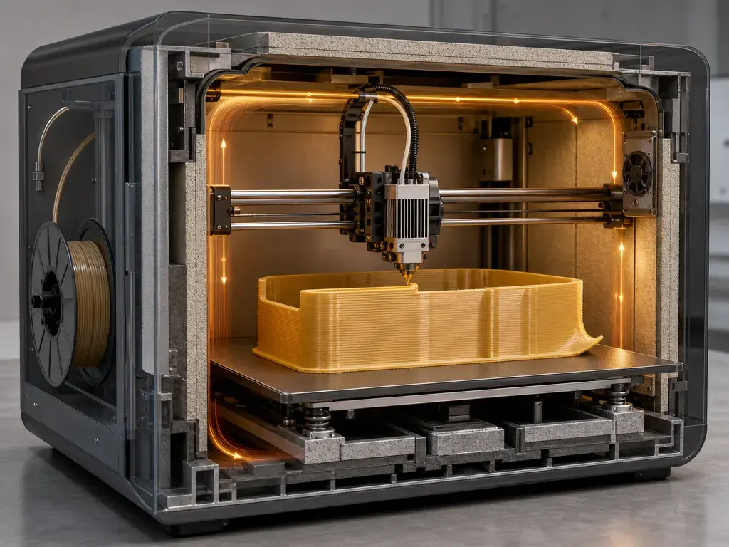
How ULTEM / PEI prints: thermal control + anisotropy
ULTEM / PEI printing is a high-temperature melt process, so the real issue is not just whether the nozzle can get hot enough. Part quality depends on whether the deposited road stays hot long enough for meaningful diffusion across the layer interface before shrinkage stress locks in. If the surface cools too quickly, residual stress rises, corners lift, and layer interfaces weaken. That is why serious PEI printing is usually a chamber-control problem, not just an extruder-temperature problem. Recent Scientific Reports work on PEI material extrusion reinforces the point: the authors reported that in-situ IR heating kept the printed-layer surface above the glass-transition temperature of 177 °C, reduced warping deformation, and improved tensile behavior in a direction-dependent way. [20]
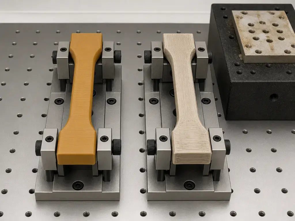
Before any strength number is meaningful, orientation has to be defined. Stratasys uses Flat (XY), On-edge (XZ), and Upright (ZX) as the canonical labels in its materials testing procedure. The same procedure also maps test methods to the property names used throughout the datasheets: tensile data to ASTM D638 Type I, flexural data to ASTM D790, Izod impact to ASTM D256, HDT to ASTM D648, and Tg to ASTM D7426. If you quote a strength value without the orientation and test context, you are leaving out part of the result. [2]
That orientation effect is not small. In the 2017 Zaldivar et al. study on ULTEM 9085, printed FDM parts ranged from 46% to 85% of comparable injection-molded strengths, and the coefficient of variation increased from 2% to 13% as the primary layer orientation deviated from the primary load direction. In practice, interlayer behavior in the build direction is often the limiting case, so a geometry that looks acceptable in one layout can underperform badly in another. [19]
Short definitions for this article:
- Tg: Glass transition temperature. In the Stratasys context here, it is reported by ASTM D7426. It marks the softening transition of an amorphous polymer, not a guaranteed use temperature. [2] [5] [6]
- HDT: Heat deflection temperature. Here it is reported by ASTM D648, and the load matters. A 66 psi result is not interchangeable with a 264 psi result. [2] [5] [6]
- Vicat: A penetration-based softening metric. For the raw-resin ULTEM 9085 page, SABIC reports Vicat B/50 at 173 °C and B/120 at 175 °C by ISO 306. [4]
- RTI: Relative thermal index. SABIC lists RTI up to 180 °C for the ULTEM resin family, but RTI is not the same as part service temperature. [3]
- UL 94: A plastics flammability evaluation standard used for parts in devices and appliances. It is not the same test regime as aircraft interior regulations. [21]
- FAR 25.853: The aircraft interior flammability context in 14 CFR §25.853, which points certain applications to Appendix F requirements. [17]
- OSU heat release: In Appendix F Part IV, the average total heat release must not exceed 65 kilowatt-minutes per square meter and the average peak heat release rate must not exceed 65 kilowatts per square meter. [18]
- Outgassing: Release of volatiles under specified test conditions. Stratasys reports ULTEM 1010 outgassing results using ASTM E595-15. [5]
None of Tg, HDT, Vicat, or RTI automatically equals service temperature. They are test-defined indicators, and the correct interpretation depends on load, time, geometry, environment, and the qualification method actually required by the application. [2] [3] [4]
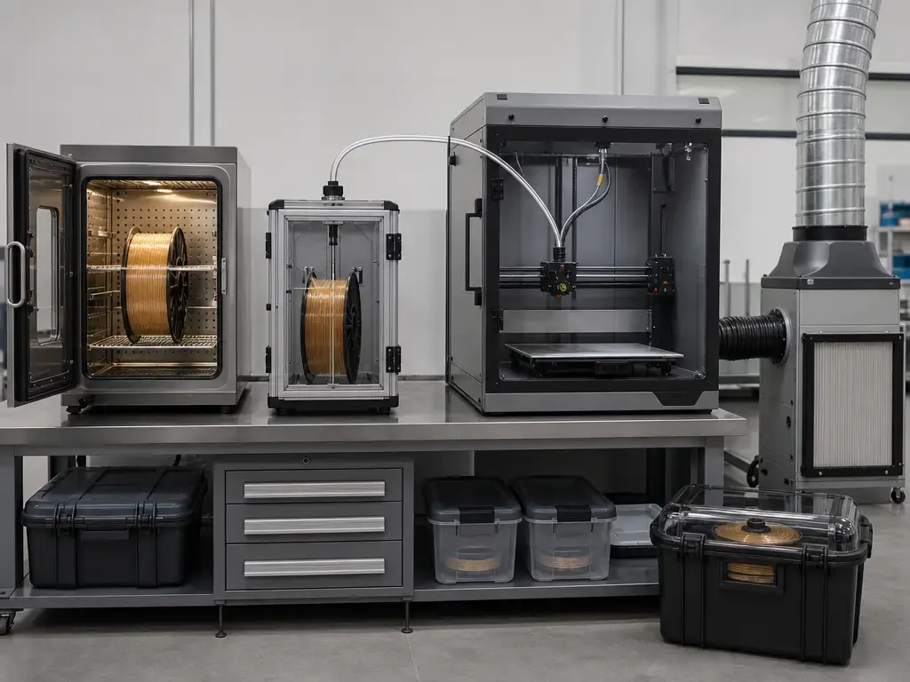
What you need for ULTEM 3D printing
PEI is not a plug-and-play desktop filament. ULTEM 3D printing is a system-level process that requires thermal capability, dry handling, and safety planning at the same time. [7] [9] [10]
At the hardware level, the key question is not the printer brand but whether the machine can actually hold the temperature ranges published for the exact filament you plan to run. Vendor guidance shows how wide the spread can be. 3DXTech’s ThermaX PEI 1010 product guidance recommends 370 to 390 °C at the extruder, 120 to 160 °C at the bed, a heated chamber as recommended, and drying at 150 °C for 4 hours. BASF Forward AM’s Ultrafuse PEI 9085 lists 340 to 360 °C nozzle temperature, 160 to 190 °C bed temperature, 160 to 180 °C build-chamber temperature, and drying at 60 °C for 4 to 16 hours. Solvay’s KetaSpire PEEK AM filament raises the burden again, listing drying at a minimum of 150 °C for 4 hours, extruder temperature of 390 to 450 °C, and bed temperature above 200 °C. The point is not to average those numbers into a universal high-temp recipe. It is that the material name alone tells you very little about the real process window. [7] [10] [12]
Drying, storage, feed path, and ventilation belong in the same discussion. Essentium’s 9085 sheet says the filament should be kept in a dry container and dried only if moisture rises above 200 ppm, using 120 to 130 °C for 4 to 6 hours in a low-dew-point or vacuum oven. That is very different from BASF’s 60 °C recommendation for Ultrafuse PEI 9085 and from 3DXTech’s 150 °C recommendation for its PEI 1010 product. The lesson is not that one vendor is wrong. It is that drying is formulation-specific and should be read from the exact TDS or SDS for the exact spool. On the safety side, the 3DXTech PEI 1010 SDS states that local exhaust is preferred and that a NIOSH approved respirator is recommended for processing fumes or dust from grinding, sanding, or sawing. [11] [7] [10] [9]
Minimum capability checklist
- Hot end rated for the filament’s published nozzle range. [7] [10] [12]
- Heated bed rated for the filament’s published bed range. [7] [10] [12]
- Controlled chamber or enclosed high-temperature build environment when the filament guidance calls for it. [7] [10]
- Dry storage and, ideally, a dry feed path for hygroscopic material. [10] [11]
- Build-surface and adhesion strategy that can tolerate the thermal load. [10] [11]
- Support strategy planned around heat, access, and post-processing, not as an afterthought. [5] [10]
- Ventilation or extraction consistent with the SDS language for the material being processed. [9]
| Material (source) | Nozzle | Bed | Chamber & drying (exact wording + caveat) |
|---|---|---|---|
| 3DXTech ThermaX PEI 1010 product guidance. [7] | 370 to 390 °C. [7] | 120 to 160 °C. [7] | Heated chamber: recommended. Drying: 150 °C for 4 hours. [7] |
| Forward AM Ultrafuse PEI 9085. [10] | 340 to 360 °C. [10] | 160 to 190 °C. [10] | Build chamber: 160 to 180 °C. Drying: 60 °C for 4 to 16 hours. [10] |
| Essentium 9085. [11] | 360 to 390 °C for recommended FDM print settings. [11] | 120 to 140 °C for recommended FDM print settings. [11] | No chamber temperature is stated in the cited FDM settings. Dry only if moisture exceeds 200 ppm: 120 to 130 °C for 4 to 6 hours. [11] |
| Solvay KetaSpire PEEK AM filament. [12] | 390 to 450 °C. [12] | Above 200 °C. [12] | No chamber temperature is stated in the cited TDS. Drying: minimum 150 °C for 4 hours. [12] |
PEI filament properties: how to read the numbers
Thermal numbers are only useful when you keep the data class attached. SABIC’s ULTEM resin family page is raw-resin family context, and it gives a family-level Tg anchor of 217 °C together with RTI and flame-behavior context. That does not mean every printed PEI part has a Tg of 217 °C. In Stratasys’s non-printed MDS data, ULTEM 1010 lists a Tg inflection of 209.37 °C and a specific gravity of 1.290 at 23 °C, while ULTEM 9085 lists 177.3 °C and 1.27 at 23 °C. SABIC’s raw-resin ULTEM 9085 page adds another layer of context with molded-material thermal values such as HDT of 169 °C at 0.45 MPa and 153 °C at 1.82 MPa, plus Vicat B/50 of 173 °C and B/120 of 175 °C. None of those values should be merged into one catch-all “PEI number.” [3] [4] [5] [6]
Mechanical data need the same discipline. First, distinguish yield from break. Second, keep machine and orientation attached. In the Stratasys ULTEM 1010 F900 T14 dataset at 0.25 mm layer height, the tensile result is reported as no yield, with strength at break of 79.2 MPa in XZ and 28.2 MPa in ZX. In the Stratasys ULTEM 9085 F900 T16 dataset at the same layer height, yield strength is reported at 69.2 MPa in XZ, while strength at break is 68.1 MPa in XZ and 39.4 MPa in ZX. These examples do not prove that one grade is simply stronger. They show that orientation can dominate the interpretation. [5] [6]
The final reading rule is the one Stratasys prints at the top of the sheet: typical values are for reference and comparison only, not design specifications or quality-control limits. If you need qualification-level evidence, print and test coupons that match the production machine, tip, layer height, and orientation profile instead of relying on a single brochure number. [5] [6]
ULTEM 9085 vs ULTEM 1010: sourced comparisons
Using Stratasys data only, ULTEM 1010 carries more thermal margin than ULTEM 9085 in both non-printed Tg and printed HDT. ULTEM 1010 is listed at 216.88 to 217.12 °C for HDT at 66 psi and 214.51 to 215.12 °C at 264 psi, while ULTEM 9085 is listed at 178.2 to 178.4 °C at 66 psi and 170.2 to 172.6 °C at 264 psi. For tooling and fixtures, that difference helps explain why 1010 is the grade Stratasys positions for autoclave-capable sterilization and composite lay-up tooling. It still does not remove the need to validate the real part under the real load case. [5] [6]
The strength comparison is just as context-sensitive. In the F900 T16 ULTEM 9085 data, strength at break is 68.1 MPa in XZ and 39.4 MPa in ZX. In the F900 T14 ULTEM 1010 data, strength at break is 79.2 MPa in XZ and 28.2 MPa in ZX. That means orientation sensitivity can outweigh any simplistic “9085 versus 1010” ranking. Stratasys’s F3300 ULTEM 1010 dataset makes the same point from another angle: the F3300 N500 example reports 91.6 MPa at break in XZ and 36.7 MPa in ZX, showing that machine and process path matter too. [5] [6] [19]
Certified-grade context matters for documentation and traceability, but it does not mean a printed part is certified by default. Stratasys states that ULTEM 9085 CG meets more stringent test criteria and provides documented traceability from filament back to the raw-material lot number. That is valuable when a program requires traceability. It is not the same as saying every printed bracket, duct, or housing is automatically approved for regulated service. [6]
| Property (method) | 9085 (Stratasys; include machine/orientation) | 1010 (Stratasys; include machine/orientation) | Design takeaway |
|---|---|---|---|
| HDT @66 psi (ASTM D648) | 178.2 to 178.4 °C, printed XY/XZ. [6] | 216.88 to 217.12 °C, printed XY/XZ. [5] | Heat margin differs by grade. |
| Strength @ break (ASTM D638) | F900 T16, 0.25 mm: XZ 68.1 MPa vs ZX 39.4 MPa. [6] | F900 T14, 0.25 mm: XZ 79.2 MPa vs ZX 28.2 MPa. [5] | Orientation dominates. |
| Traceability / machine note | 9085 CG, F900 T16A, 0.25 mm: break XZ 73.9 MPa vs ZX 55.3 MPa. [6] | 1010, F3300 N500, 0.25 mm: break XZ 91.6 MPa vs ZX 36.7 MPa. [5] | CG matters for traceability; machine context still changes the result. |
Filled PEI grades (CF / GF) — optional depth, but sourced
Filled PEI exists because filler can change stiffness, thermal response, and printed-part behavior. But the safest way to discuss it is by named product, not by broad generalization. A 3DXTech carbon-filled example, CarbonX CF Ultem 9085, lists Tg at 186 °C and HDT at 165 °C at 0.45 MPa, with printed-specimen conditions of 390 °C extrusion, 140 °C bed temperature, and XY-flat orientation. A separate 3DXTech glass-filled example, FibreX PEI GF30, lists Tg at 217 °C and HDT at 212 °C at 0.45 MPa, with printed-specimen conditions of 380 to 410 °C extrusion, 130 to 140 °C bed temperature, and XY-flat orientation. These are product examples, not universal filled-PEI rules. [15] [16]
The interpretation limit matters most. Filler does not erase chamber sensitivity, drying requirements, or the risk of warping and layer-interface weakness. It can also change abrasion behavior and post-processing response. A filled grade should therefore be treated as its own material system with its own TDS, not as a drop-in extension of plain PEI. [15] [16]
PEI vs PEEK filament: which is better?
There is no universal winner in the PEI vs PEEK decision. The better material is the one that matches the part requirement, the machine’s thermal envelope, and the amount of qualification work you can actually support. PEI-based ULTEM printing is often the more practical route when the application needs high heat resistance and flame-behavior context but the printer and workflow cannot tolerate the more demanding semi-crystalline processing window. [3] [12] [13]
The structure difference is the key divider. PEI is amorphous, so it does not go through the same crystallization-driven shrinkage behavior as PEEK during cooling. PEEK is semi-crystalline, and Victrex AM 450 FIL lists a glass-transition onset of 143 °C, a midpoint of 150 °C, and a melting temperature of 343 °C. That extra upper-end thermal headroom can be valuable, but it comes with a harder process. Solvay’s KetaSpire AM filament TDS lists drying at a minimum of 150 °C for 4 hours, extrusion at 390 to 450 °C, and bed temperature above 200 °C. Even 3DXTech’s PEEK TDS, which is framed as printed-specimen conditions rather than a universal setup guide, still uses 380 to 400 °C extrusion and 130 to 140 °C bed temperature with XY-flat specimens. The spread itself is the lesson: PEEK usually asks for more machine margin and more process control than PEI. [12] [13] [14] [3]
| Question | PEI / ULTEM (amorphous) | PEEK (semi-crystalline) | Guidance |
|---|---|---|---|
| Key thermal anchors | Family-level raw-resin Tg anchor 217 °C; grade examples vary, including 177.3 °C for 9085 and 209.37 °C for 1010 in Stratasys non-printed MDS data. [3] [5] [6] | Tg onset 143 °C, midpoint 150 °C, melting temperature 343 °C. [13] | Use grade plus data class, not a generic polymer label. |
| Print consistency risk | Still high and chamber-sensitive. [7] [10] | Adds crystallization and shrinkage management on top of high heat. [12] [13] | Choose by machine capability and validation plan. |
| FST / regulatory context | Material-grade FST reporting exists, but part qualification is still required. [4] [17] [18] | Application-specific and not interchangeable with PEI claims. [12] [13] | Do not transfer compliance from one polymer family to another. |
Applications (conditional examples only)
Transportation interiors are the classic example, but the wording has to stay disciplined. SABIC’s raw-resin ULTEM 9085 page reports FAR 25.853 A/B values of less than 5 and OSU values of 55 or lower for total heat release at 2 minutes and peak heat release rate at 5 minutes. The regulatory framework itself comes from 14 CFR §25.853 and Appendix F, where certain components must meet additional Appendix F Parts IV and V requirements. That makes PEI / ULTEM relevant to aircraft interior conversations, not automatically approved for any specific printed part. [4] [17] [18]
Tooling and fixtures are the cleaner application case. Stratasys explicitly positions ULTEM 1010 for autoclave-capable sterilization and composite lay-up tooling. That points to jigs, trays, lay-up tools, and other process hardware where temperature stability and repeatability matter more than low-cost printability. Even here, the useful statement is “positioned for,” not “approved for,” because the part still has to survive the actual thermal, chemical, and dimensional cycle of the job. [5]
Industrial jigs, housings, and electronics-adjacent enclosures also make sense when the part needs more heat resistance or flame-retardant context than a standard engineering filament can provide. But unless the application source gives a specific medium, temperature, and duty cycle, the right claim remains modest: PEI can be relevant here, provided the process and validation burden are acceptable. [3] [10]
Limitations + failure modes
The common failure modes are tightly connected. Warping and corner lift come from thermal gradients and contraction. Delamination and weak Z-direction behavior come from limited interlayer diffusion when the interface cools too fast or the load path is poorly aligned with the bead structure. Moisture can create unstable extrusion, bubbles, and poor surface finish. Support scarring becomes more visible when high interface temperatures and strong support contact are combined on complex geometry. Long prints can also drift if nozzle, bed, or chamber conditions are not stable over time. The recent PEI IR-heating study matters because it directly links better local thermal control with reduced warping deformation and improved interlayer bonding. [20] [11] [19]
The production warning is simple: one successful print does not prove a reliable process. High-temperature filament needs repeatable drying, repeatable thermal history, and inspection habits that match the part’s risk. A practical first check is to print matched coupons alongside the first real geometry and compare bonding, distortion, and mechanical response before the part goes any further. [5] [11] [19]
Failure mode → likely cause → mitigation
- Corner lift → thermal gradient and contraction → hotter or more stable chamber conditions, geometry changes, better first-layer strategy, and slower cooling. [10] [20]
- Z weakness → limited interlayer diffusion → re-orient the part, improve thermal control, and validate a hotter or more stable process profile. [19] [20]
- Bubbles / poor surface → moisture uptake → dry storage, dry feed path, and vendor-specific drying protocol rather than a generic rule. [7] [10] [11]
- Support damage → overly aggressive support contact or difficult access → redesign support interfaces and removal strategy before the print starts. [5] [10]
- Dimensional drift → shrinkage, residual stress, or process drift → calibration coupons, compensation, and dimensional inspection as part of the workflow. [19] [20]
Current research + qualification burden
ULTEM 3D printing carries a real qualification burden because the material response is strongly path-dependent. The Zaldivar study remains a useful warning sign: when identical ULTEM 9085 geometries were printed in different orientations, strength utilization ranged from 46% to 85% of comparable injection-molded values and variability penalties rose from 2% to 13%. That kind of spread means qualification work is not just about proving the polymer; it is about proving the process route. [19]
The 2026 PEI IR-heating paper points toward where process development is going. The authors reported that keeping the layer surface above Tg locally improved diffusion, reduced warping, and improved tensile behavior, especially in the transverse direction. In practice, that suggests local thermal management and monitoring may become more important than treating the chamber as a single bulk-temperature box. [20]
When ULTEM 3D printing makes sense
ULTEM 3D printing makes sense when the part has a real material requirement that justifies the process burden. The ULTEM resin family is positioned around high heat resistance, RTI up to 180 °C, LOI of 47%, and thin-wall UL 94 V-0 performance in many grades, so there are legitimate reasons to choose it. The mistake is choosing it only because it sounds advanced. [3]
The practical decision order is requirements first, then machine capability, then validation burden. If the printer cannot hold the thermal window, the drying workflow is inconsistent, or the ventilation plan is missing, the material choice is already wrong. If the application genuinely needs the heat resistance or flame-behavior context and the process can be controlled, then PEI / ULTEM becomes defensible. The SDS burden is part of that decision too, since the cited PEI 1010 SDS says local exhaust is preferred. [9] [3]
Decision checklist
- Use PEI / ULTEM when heat resistance, flame-behavior context, chemical resistance, or stiffness actually justify the machine and handling burden. [3]
- Avoid it if you cannot control the build environment, if Z-direction weakness is unacceptable without redesign, or if traceability or documentation is required but unavailable. [6] [19]
- Test coupons that match the real orientation, printer, tip, layer height, and profile before treating any value as decision-grade. [5] [6]
FAQ
What is PEI (ULTEM) filament in 3D printing?
PEI filament is polyetherimide used in filament-based material extrusion. ULTEM is SABIC’s trademarked resin family within that broader PEI category, so the terms overlap in practice but are not identical. In buying language, call it PEI when you mean the polymer family, and call it ULTEM when the supplier documentation actually states that SABIC ULTEM resin is used. [3] [7] [10]
Is ULTEM 9085 the same as ULTEM 1010?
No. They are different grades with different positioning and different reported properties. Stratasys positions ULTEM 1010 for higher-heat tooling and sterilization-linked use, while ULTEM 9085 is commonly discussed in FST and transportation-related contexts. Their Stratasys MDS values also differ materially: 1010 has higher listed Tg and higher printed HDT than 9085 in the cited OEM data. [5] [6]
What do you need for ULTEM 3D printing?
At minimum, you need a printer that can reach the published nozzle and bed range for the exact filament, plus a controlled build environment and a drying workflow that matches that spool’s TDS. For example, 3DXTech and BASF publish different PEI settings, and Essentium uses a moisture-triggered drying rule. That variation is the point: follow the exact material documentation, not an internet average. [7] [10] [11]
Why do ULTEM tensile strengths differ so much between XY, XZ, and ZX?
Because FDM / FFF parts are anisotropic. In Stratasys’s convention, Flat (XY), On-edge (XZ), and Upright (ZX) are different build orientations, and the bead-to-bead and layer-to-layer interfaces are not mechanically equivalent. Stratasys data for both 1010 and 9085 show large XZ/ZX gaps, and peer-reviewed work on 9085 found both lower strength utilization and higher variability as orientation moved away from the primary load direction. [2] [5] [6] [19]
What’s the difference between UL 94 V-0 and FAR 25.853 / OSU heat release?
UL 94 is a plastics flammability classification standard used for parts in devices and appliances. FAR 25.853 is aircraft-interior regulation, and Appendix F adds test methods such as the OSU heat-release test for certain components. Appendix F Part IV sets 65 kW-min/m² and 65 kW/m² as the average limits. So a UL 94 V-0 result does not automatically satisfy an aircraft interior requirement. [21] [17] [18]
Does PEI / ULTEM filament need drying, and how do I choose a drying temperature?
Yes, but the correct drying temperature is formulation-specific. 3DXTech’s PEI 1010 product guidance uses 150 °C for 4 hours, BASF’s Ultrafuse PEI 9085 uses 60 °C for 4 to 16 hours, and Essentium 9085 says to dry only if moisture rises above 200 ppm, using 120 to 130 °C for 4 to 6 hours. Use the exact vendor document for the exact spool. [7] [10] [11]
PEI vs PEEK filament: how do I decide for my application?
Start with the requirement, then check the printer. PEI is often the more manageable high-temperature choice because it is amorphous and avoids PEEK’s crystallization-driven process burden. PEEK can offer more upper-end thermal capability, but the cited vendor sheets also show a tougher window, including drying at 150 °C minimum, 390 to 450 °C extrusion, and bed temperatures above 200 °C in one Solvay example. [12] [13] [14] [3]
Sources
- ISO/ASTM 52900:2021 vocabulary page
- Stratasys Materials Testing Procedure 0121a
- SABIC ULTEM resin family description
- SABIC Material Finder ULTEM resin 9085
- Stratasys MDS FDM ULTEM 1010 Resin 0626a
- Stratasys MDS FDM ULTEM 9085 Resin 0426a
- 3DXTech ThermaX PEI 1010 product page
- 3DXTech ThermaX PEI 1010 TDS Rev 4.0
- 3DXTech ThermaX PEI 1010 SDS V2.1
- Forward AM Ultrafuse PEI 9085 TDS v1.0
- Essentium 9085 TDS v1.0
- Solvay KetaSpire MS NT1 AM Filament TDS
- Victrex AM 450 FIL datasheet page
- 3DXTech ThermaX PEEK TDS Rev 3.0
- 3DXTech CarbonX CF Ultem 9085 TDS Rev 1.0
- 3DXTech FibreX PEI GF30 TDS Rev 1.0
- eCFR mirror 14 CFR 25.853
- eCFR mirror 14 CFR Part 25 Appendix F
- Zaldivar et al. 2017 ULTEM 9085 orientation effects
- Lee et al. 2026 IR heating for high-temperature MEX of PEI
- UL Solutions overview listing UL 94 as plastics evaluation standard