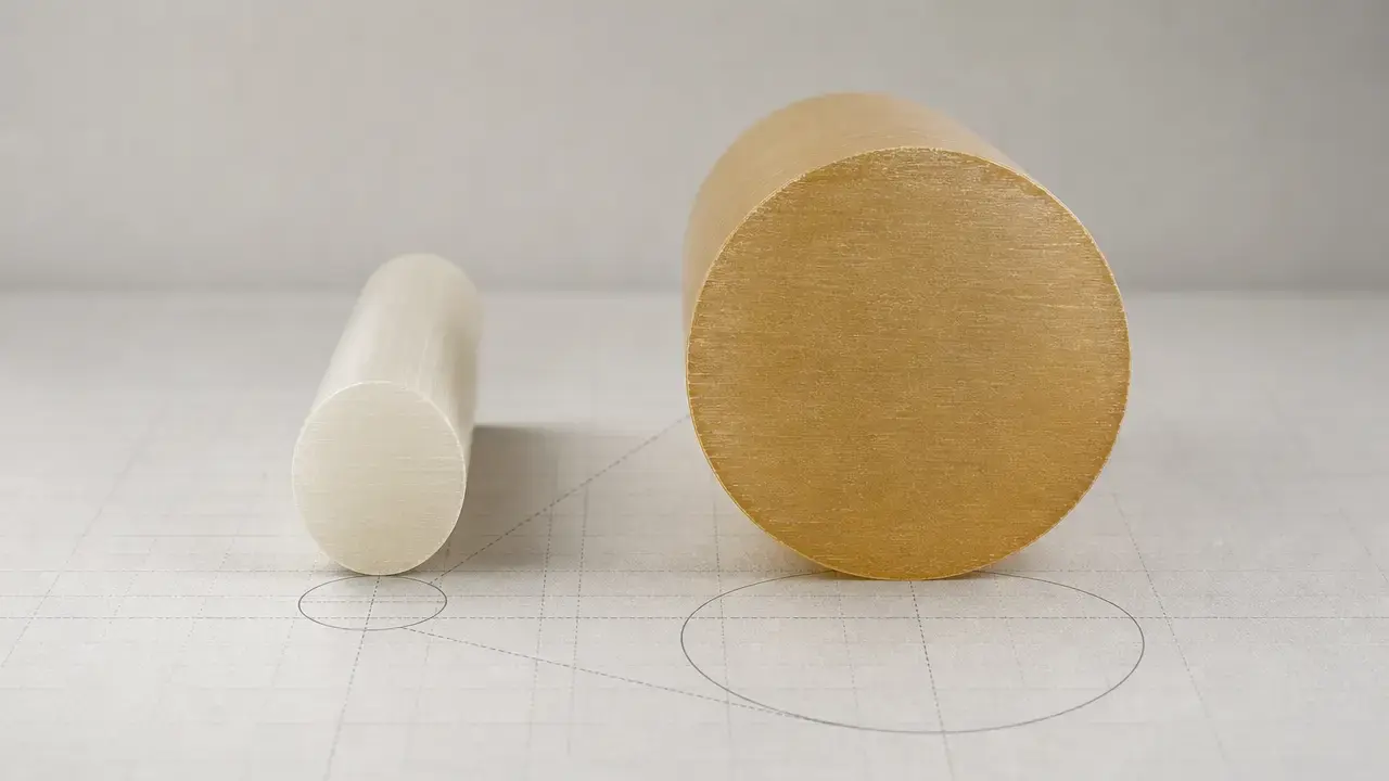

Summary: filament diameter
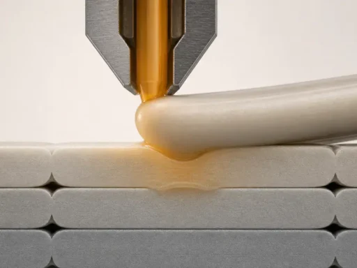
Filament diameter is the nominal outside diameter of the plastic strand fed into an FFF/FDM printer. The two common nominal sizes are 1.75 mm and 2.85 mm, with 2.85 mm commonly called “3 mm.” [3]
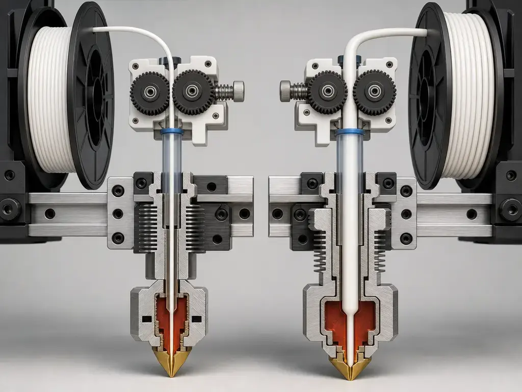
What matters in practice is fit and flow, not the label alone. Most printers are built around one filament family through the full feed path, from the spool guide and feeder to the guides or tubes, heatbreak bore, hotend inlet, and nozzle melt zone. Diameter also affects extrusion math, because slicers and some firmware features use it when converting filament movement into deposited volume. Real filament can vary along its length and can be slightly out of round, so tolerance, local variation, and ovality all matter. [3] [11] [12]
- Most printers are built for either 1.75 mm or 2.85 mm, so you usually cannot swap sizes without hardware or filament-path changes. [3] [6]
- 2.85 mm is often called “3 mm,” but you should still check the exact machine or material specification. [3] [16]
- A small diameter error becomes a larger flow error because filament area scales with diameter squared.
What filament diameter means (nominal vs measured vs ovality)
The first distinction is between the label and the strand in your hand. Here, nominal diameter means the stated outside diameter on the spool or datasheet. Measured diameter is what you read at a specific point on the filament. Diameter variation is how that measured value changes along the length. Ovality means the filament is out of round, so a cross-section can measure differently depending on the axis. Prusament’s manufacturing page illustrates why this matters: it describes inline measurement at 4700 times per second in two perpendicular axes. [8] [9]
Tolerance is related, but it is not the same as average diameter. A spool can average close to nominal and still contain thin spots, thick spots, or out-of-round sections that affect feeding or melting. Sola’s 2022 review treats diameter consistency as a printability issue, not just a labeling detail, and MatterControl likewise recommends measuring multiple points instead of trusting one quick caliper reading. [9] [13]
Terms you must not mix up:
- Filament diameter vs nozzle diameter.
- Nominal diameter vs measured diameter.
- Tolerance vs local variation.
- Tolerance vs ovality or out-of-round filament.
- Diameter setting vs extrusion multiplier vs E-steps.
Why 1.75 mm and 2.85 mm (“3 mm”) exist
The short answer is naming inertia, not a promise that every “3 mm” filament is exactly 3.00 mm. Prusa’s glossary says the two common diameters are 1.75 mm and 2.85 mm, with 2.85 mm commonly called 3 mm. ColorFabb says it manufactures 2.85 mm filament but sometimes refers to 3.00 mm “to keep things simple.” UltiMaker’s older educational material adds the legacy context: early 3D printing often reused plastic welding filament sold as 3 mm, and Bowden-based machine design also helped keep that family in use. That is enough historical context for practical use without claiming a single universal origin story. [3] [16] [17]
Filament diameter and extrusion volume: the math that makes it matter
Slicers and firmware do not treat filament diameter as a cosmetic label. They use it in the conversion from required printed volume to commanded filament length. Cura’s material_diameter definition says to match the setting to the diameter of the filament being used, and Marlin documents nominal filament diameter values such as 1.75, 2.85, and 3.0 in its own calculation path for volumetric and width-compensation contexts. [11] [12]
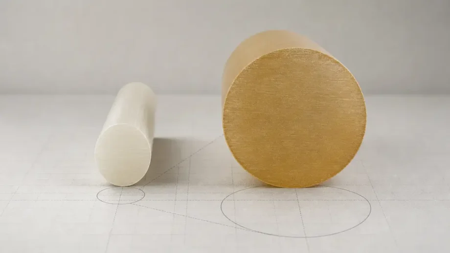
For idealized calculations, use A = π(d/2)², which assumes perfectly round filament. In this article, calculated areas and ratios are rounded to 4 significant figures, and percentage examples are rounded to two decimals. Using the common nominal sizes, A(1.75 mm) = 2.405 mm² and A(2.85 mm) = 6.379 mm². That makes the 2.85 mm strand 2.652× larger by cross-sectional area, not by diameter. [3]
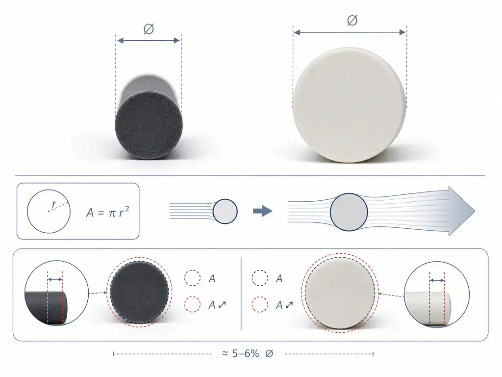
That square-law relationship is why small diameter errors matter. If a workflow assumes 1.75 mm but the actual filament is 1.80 mm, the cross-sectional area rises by about +5.80%. If the actual filament is 1.70 mm, it falls by about −5.63%. Around a nominal 1.75 mm strand, 1.78 mm ≈ +3.46% and 1.72 mm ≈ −3.40%. Those shifts are large enough to change line fill and consistency before you even get into moisture, nozzle issues, or feeder slip.
Key variables affected by filament diameter:
- Commanded filament length for a given printed volume.
- Volumetric flow rate and melt pressure.
- Feeder grip and pinch reliability. [9]
- Melting behavior and residence time in the hotend. [9]
- Sensitivity to tolerance and ovality.
1.75 mm vs 2.85 mm filament: compatibility and real-world trade-offs
The correct size is the one the printer’s physical path was built for. That path includes the spool guide, feeder or drive gears, guides or tubes, heatbreak bore, hotend inlet, and nozzle melt zone. These parts are not automatically interchangeable. E3D’s V6 HeatBreak page is a straightforward example: the part is sold in diameter-specific variants rather than one universal size. [6]
Trade-offs exist, but they are conditional. Sola’s review notes that Bowden-drive printers are not the optimal choice for very flexible or soft materials, and says filaments for Bowden-drive printers often have a diameter of 2.85 mm for the same reason. At the same time, current printer ecosystems show both families in normal use: the Original Prusa MK4S specifies 1.75 mm filament, while UltiMaker’s S-series PLA is specified at 2.85 mm. It is better to read this as two mechanical ecosystems than as a universal ranking. [4] [5] [9]
| Criterion | 1.75 mm | 2.85 mm (“3 mm”) | Notes / required citation |
|---|---|---|---|
| Nominal cross-sectional area | 2.405 mm². | 6.379 mm². | 2.85 mm is 2.652× larger by area, using the nominal sizes in [3]. |
| Common example ecosystem | Prusa MK4S uses 1.75 mm. [4] | UltiMaker S-series PLA is 2.85 mm. [5] | These are ecosystem examples, not market-share claims. |
| Bowden + flexible materials | Depends on machine design and material stiffness. | Often associated with Bowden ecosystems in the literature. [9] | Sola says Bowden printers are not optimal for very flexible materials and often use 2.85 mm filament. [9] |
| Interchangeability | Usually not without hardware or path changes. [6] | Usually not without hardware or path changes. [6] | Diameter compatibility is a physical-path issue, not just a profile setting. [3] [6] |
Read that table as geometry plus fit. The area difference changes how much plastic is carried per millimeter of feed, but the practical answer still depends on the machine’s filament path and the materials it is expected to handle. [9]
Slicer vs firmware vs tuning: where filament diameter is used (and misused)
Many support threads mix together five different controls: the slicer’s filament diameter, flow or extrusion multiplier, E-steps, firmware volumetric mode, and width-sensor compensation. Those settings interact, but they do different jobs. Cura defines material_diameter as the diameter of the filament used and shows a default value of 2.85 mm in the definition file. Marlin separately documents a nominal filament diameter setting and explains how it is used in volumetric and compensation features. [11] [12]
The basic rule is simple: match the nominal filament family first, then tune the rest. Marlin explicitly says that if you use 1.75 mm filament that physically measures 1.70 mm, you should still use 1.75 if that is what your slicer is set to. Its M404 command exists to set the nominal width used for filament-width auto-flow, and the documentation says that value should match the slicer’s value. [10] [11]
| Setting / feature | Where it lives | What it actually controls | Common mistake to warn against |
|---|---|---|---|
Filament diameter (material_diameter) |
Slicer. | Converts required print volume into filament length. [12] | Using it to hide a hardware mismatch instead of matching the actual filament family first. |
| Extrusion multiplier / Flow % | Usually slicer or printer UI. | Fine scalar adjustment after the basic setup is correct. | Using flow to compensate for obviously inconsistent filament or the wrong nominal size. |
| E-steps / extruder calibration | Firmware. | Motor steps per commanded filament motion. | Treating motion calibration like a material-diameter setting. |
| Volumetric extrusion mode | Firmware. | Uses volume-based extrusion commands and still depends on coherent nominal diameter settings. [11] | Forgetting that slicer and firmware still need matching assumptions. |
| Filament width sensor compensation | Firmware feature. | Dynamic flow adjustment from measured filament width. [11] | Assuming a runout sensor can do the same job. |
If those roles stay separate, troubleshooting gets easier. Diameter tells the math what filament family is being used, E-steps calibrate motion, flow trims output, volumetric mode changes the basis of extrusion, and width-sensor compensation is a separate runtime correction layer. [11] [12]
Filament diameter tolerance: what it means (and what it doesn’t)
Filament diameter tolerance is a stated plus-or-minus band around the nominal size. A manufacturer technical data sheet is the clearest example because it is tied to a specific product. Prusament’s PLA technical data sheet, last updated on 2022-02-16, lists 1.75 ± 0.02 mm, with ± 0.03 mm for PLA Blend. That is a product claim for that material family, not a universal industry rule. [7]
Different source types need to be read differently. A technical data sheet is a product-specific specification. A manufacturer process page can add broader claims, but those remain manufacturer claims: Prusament says the “industry standard” is ±0.05 mm while also stating its own tighter ±0.02 mm limit, or ±0.03 mm for blended materials. A literature review gives a different kind of context: Sola writes that commercial printers use filaments of either 1.75 ± 0.1 mm or 2.85 ± 0.1 mm. ColorFabb also states a 0.05 mm tolerance claim for its 2.85 mm line. None of those sources should be turned into a universal pass/fail threshold for every spool and printer. [7] [8] [9] [16]
No single publicly verifiable universal acceptable tolerance was found. In practice, tolerance depends on source class, hardware path, material stiffness, flow demand, and how sensitive the job is to inconsistent extrusion. [9] [11]
Tolerance claims to treat differently:
- Manufacturer guaranteed spec in a technical data sheet.
- Manufacturer marketing claim such as “industry standard.”
- Scientific literature context.
- Your measured average.
- Local spikes or thin spots along the length.
- Ovality vs simple diameter variation.
How to measure filament diameter (and how honest to be about your tools)
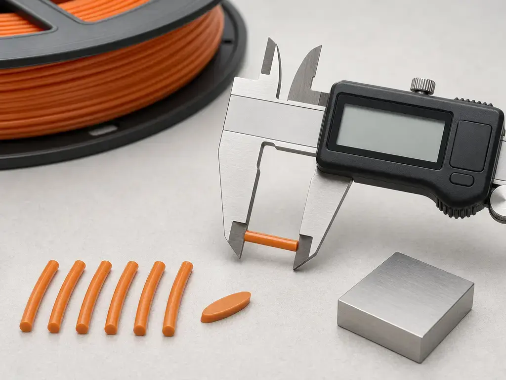
If you want a useful manual number, measure more than one spot and average the result. MatterControl’s help says filament can vary by ±0.1 mm, recommends measuring with calipers, and suggests checking several spots along the spool instead of trusting one reading. Its older wiki gives a simple rule of thumb: measure five times, discard the highest and lowest values, and average the remaining three. That is practical diagnostic advice, not a standard. [13] [14]
Manual measurement is best treated as diagnostic-first. Soft filament can be slightly flattened by heavy caliper pressure, and a single spot can hide both along-length variation and ovality. If your firmware uses a nominal diameter for volumetric or width-sensor features, Marlin says that nominal value should stay aligned with the slicer. Printer and material pages still publish nominal families this way: for example, the Prusa MK4S is a 1.75 mm machine, while UltiMaker S-series PLA is a 2.85 mm material. [4] [5] [11]
- Confirm the printer or toolhead’s nominal filament family from the manufacturer specification. [4] [5]
- Confirm that the slicer’s filament diameter setting matches that nominal family. [12]
- Measure the filament at several points along the strand and average the result instead of trusting one spot. [13]
- At some points, rotate the filament 90° and measure again to check for ovality or out-of-round sections. [8]
- If your workflow expects a measured average, enter it consistently; otherwise keep the nominal value coherent across slicer and firmware. [11]
- Tune extrusion multiplier or flow separately, after diameter and hardware compatibility are already correct. [11]
- Re-check when you change spool, brand, material family, or when a spool starts behaving differently from its label. [13]
Sensors: runout vs motion vs width/diameter sensing (taxonomy + limits)
Not every “filament sensor” measures diameter, and not every sensor can change flow. A runout sensor reports presence or absence. A motion or jam sensor looks for filament movement through the path. A width or diameter sensor attempts to measure the strand itself. In Marlin, that last category can be tied to automatic flow correction, and the documentation says the feature supports only a single extruder. The same Marlin page also gives example width limits for a 1.75 mm setup of roughly 1.60 to 1.90 mm. Research on filament-geometry monitoring continues, but no reliable general accuracy figure is presented here from the accessible sources. [11] [20]
| Sensor type | Detects | Typical output | Automatically changes flow? |
|---|---|---|---|
| Runout sensor | Filament presence or absence. | Pause or prompt. | Usually no. |
| Motion/jam sensor | Whether filament is actually moving. | Pause or error state. | Usually no. |
| Width/diameter sensor | Measured filament width. | Firmware-side compensation. | Sometimes, for example in Marlin. [11] |
Troubleshooting: diameter-related symptoms (fast matrix)
Diameter is only one common cause of inconsistent extrusion. Moisture, partial clogs, poor PTFE cuts, low temperature, bad idler tension, and path friction can produce similar symptoms. Still, diameter is worth checking early because the literature gives distinct mechanisms for too-thin and too-thick filament: thin filament can lose pinch force and transfer heat poorly in the liquefier, while thick filament can raise feed resistance and clog risk. [9]
| Symptom | Diameter-related cause | Non-diameter lookalikes | What to check first |
|---|---|---|---|
| Underextrusion / gaps | Filament thinner than assumed, or local thin spots. | Partial clog, low temperature, too much speed, wet filament. | Verify slicer diameter, then measure several points and inspect the nozzle. |
| Overextrusion / blobs | Filament thicker than assumed, or wrong diameter entry. | Flow set too high, wrong line width, calibration drift. | Confirm the profile first, then measure for thickness and ovality. |
| Extruder clicking | Thick spots or too much resistance in the path. | Heat creep, idler tension problems, debris, poor tube alignment. | Check the filament path and whether the hotend parts match the intended diameter family. |
| Random layer roughness | Diameter swings or out-of-round sections. | Cooling inconsistency, Z artifacts, uneven unwind drag. | Measure along the length and inspect how the spool unwinds. |
Use the matrix as a first-pass filter, not a verdict. If the problem changes with spool position, local variation becomes more likely; if it improves after drying or path cleaning, moisture or friction may be the better explanation. [9]
Can I swap sizes? (1.75 in 2.85 printer, and vice versa)
Usually no. Casual swapping is not how most FFF printers are designed to work. The feed path, grip, and hotend geometry are built around one filament family, and diameter-specific parts such as heatbreaks are sold accordingly. In practical terms, trying to push 3 mm-family filament into a 1.75 mm path is usually a jam risk, while running 1.75 mm in a path designed around 2.85 mm can create grip, guidance, and melting problems. [6] [9]
There is a documented manufacturer-specific exception, and it should stay framed that way. LulzBot says its printers are designed for 3 mm (2.85 mm) filament by default, but that some setups can print 1.75 mm filament with no hardware modifications. The same page also says LulzBot recommends and supports 3 mm filament, and warns that TPUs and nylons will always buckle in stock toolheads in its testing and experience. That is useful as a narrow exception, not as a universal compatibility rule. [15]
Current research and market context (keep claims constrained)
Recent research still treats filament diameter as a process-control variable, not just a catalog specification. A 2026 journal paper studies how melting zone length and filament diameter affect extrusion force and maximum achievable volumetric flow rate for PLA, and the MDPI page lists a publication date of 2026-07-01. Specific force or throughput numbers are intentionally omitted here because no reliable figure was confirmed from the accessible abstract-level source alone. [20]
The standards backdrop is useful only at a high level. ISO/ASTM 52903-1:2020 exists as a feedstock-related standard reference, and ISO/ASTM 52900:2021 exists as a vocabulary reference. Those catalog pages confirm that a standards framework exists, but they should not be read as public proof of a universal hobby-filament tolerance rule. [1] [2]
Key takeaways: choosing and setting filament diameter
Filament diameter is best treated as a hardware-and-settings match. In everyday FFF use, the practical questions are straightforward: which nominal family your printer was built for, whether the slicer and firmware agree, and whether the spool is geometrically consistent enough to feed and melt predictably. The common families remain 1.75 mm and 2.85 mm, with 2.85 mm often sold or discussed as “3 mm.” [3] [6] [11]
- Buy the diameter your printer or toolhead specifies. [4] [5]
- Treat “3 mm” as the 2.85 mm family unless the manufacturer clearly specifies otherwise. [3] [16]
- Consistency, meaning low variation and low ovality, matters as much as the nominal number. [8] [9]
- Measure suspect filament before changing flow settings. [13] [14]
- Use extrusion multiplier after the correct diameter and hardware setup are in place, not instead of them. [11] [12]
FAQ
What is filament diameter in 3D printing?
Filament diameter is the nominal outside diameter of the plastic strand fed into an FFF/FDM printer. The two common sizes are 1.75 mm and 2.85 mm, with 2.85 mm commonly called 3 mm. [3]
1.75 mm vs 2.85 mm filament: which is better?
Neither is universally better. The better choice is the one your printer’s filament path was designed around. The literature also notes that Bowden-drive systems can be less suitable for very flexible materials and often use 2.85 mm filament, while modern printer ecosystems still exist for both sizes. [4] [5] [9]
Can I use 1.75 mm filament in a 2.85 mm printer?
Usually not as a casual swap. The path, grip, and hotend geometry are normally built around 2.85 mm parts. LulzBot documents some machine-specific 1.75 mm use without hardware changes, but frames it as an advanced-user exception and still recommends 3 mm filament by default. [6] [15]
Can I use 3 mm filament in a 1.75 mm printer?
Usually no. In most cases that is a physical mismatch, not a tuning problem, and it is a strong jam risk because the path is built for the smaller filament family. [6]
What is acceptable filament diameter tolerance for 3D printing?
There is no single publicly verifiable universal number. A product data sheet may promise one tolerance for one filament line, such as Prusament’s 1.75 ± 0.02 mm example, while the literature gives broader context such as 1.75 ± 0.1 mm or 2.85 ± 0.1 mm for commercial printers. Read tolerance claims by source class, not as one rule for every spool. [7] [9]
Expert: how does diameter error translate into flow error, and why does it scale with d²?
Because the relevant cross-section is circular, the idealized area is A = π(d/2)². If everything else stays the same, a larger actual diameter means more plastic per millimeter of filament, and a smaller actual diameter means less. Around 1.75 mm, using 1.80 mm instead gives about +5.80% more area, while 1.70 mm gives about −5.63% less. That is why a small diameter error can become a noticeably larger flow error. [3]
Expert: what’s the difference between slicer diameter, Marlin volumetric mode, and Marlin width-sensor compensation?
They are three different layers. The slicer’s filament diameter tells the slicer how much filament length is needed for a target printed volume. Marlin’s volumetric mode changes how extrusion is handled in firmware, but still relies on a coherent nominal diameter value. Width-sensor compensation is a separate Marlin feature that adjusts flow in response to measured filament width, and Marlin’s M404 documentation says that nominal width should match the slicer value. [10] [11] [12]
Sources
- ISO/ASTM 52903-1:2020 catalog page — ISO catalog page; Edition 1, publication date 2020-04, 6 pages.
- ISO/ASTM 52900:2021 catalog page — ISO catalog page; Edition 2, publication date 2021-11, 28 pages.
- Prusa glossary: 1.75 mm — manufacturer glossary page.
- Original Prusa MK4S product specification — manufacturer product specification page.
- UltiMaker S-series PLA material page — manufacturer material specification page.
- E3D V6 HeatBreak product page — manufacturer product page for diameter-specific heatbreak variants.
- Prusament PLA technical data sheet — manufacturer technical data sheet; last update 2022-02-16.
- Prusament: How it’s made — manufacturer process page with inline diameter-measurement claims.
- Sola (2022), Materials Requirements in Fused Filament Fabrication: A Framework for the Design of Next-Generation 3D Printable Thermoplastics and Composites — peer-reviewed open-access review article.
- Marlin M404 G-code documentation — official firmware documentation for nominal filament width in sensor compensation.
- Marlin configuration documentation — official firmware documentation; rolling page, accessed 2026-07-15.
- Cura
fdmextruder.def.jsonmaterial_diameterdefinition — official open-source definition file; rolling, accessed 2026-07-15. - MatterControl Help: Filament setting — software help page; accessed 2026-07-15.
- MatterControl wiki: Diameter property — migrated wiki page with manual measurement rule of thumb; accessed 2026-07-15.
- LulzBot: Printing with 1.75 mm filament — manufacturer guidance page; published 2018-06-19.
- ColorFabb support: 2.85 mm vs 3.00 mm naming explanation — manufacturer support article; updated 2024-02-26.
- UltiMaker schooling – 3D printing — manufacturer educational article; accessed 2026-07-15.
- UMD Statics course notes — open course notes for buckling and section-property context.
- NISTIR 6779 technical report — NIST technical report PDF for Euler-buckling formula context.
- High-Throughput Fused Filament Fabrication of PLA: Effects of Melting Zone Length and Filament Diameter on Extrusion Force and Volumetric Flow Rate — journal landing page/abstract; published 2026-07-01.