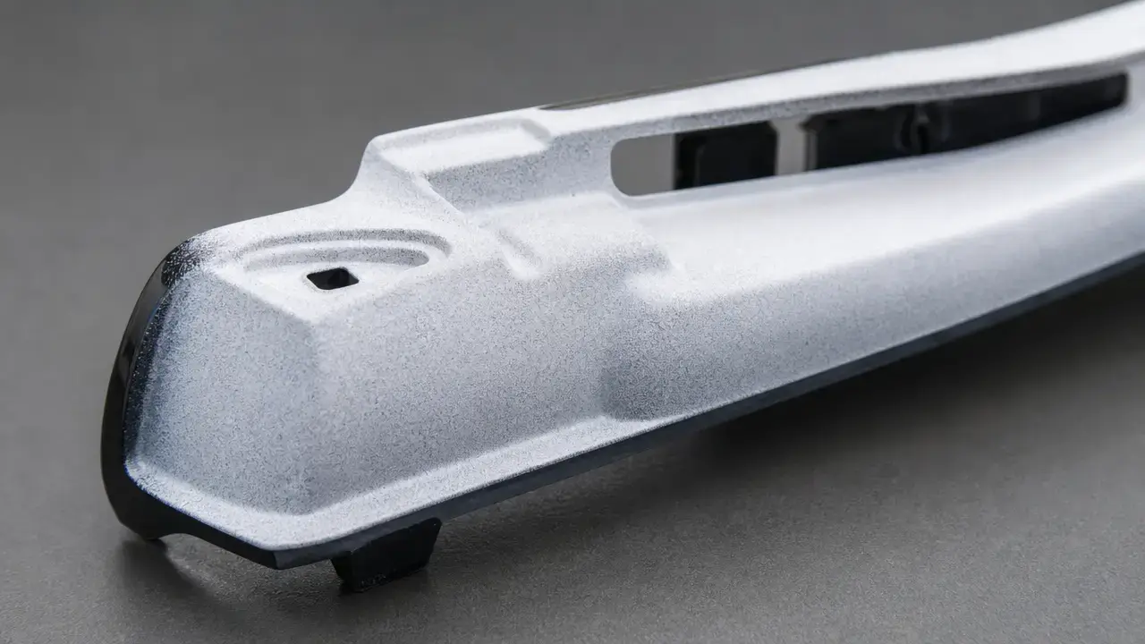

Summary: Is Artec Space Spider the best 3d scanner for car parts?
For small detailed car parts, Artec Space Spider can still be a strong option, but it is not automatically the best 3d scanner for car parts. Its manufacturer specs list up to 0.05 mm 3D accuracy and up to 0.1 mm 3D resolution, and current Artec Studio tech specs list Space Spider among discontinued models that remain compatible with the software. [1] [5]
The answer changes once part size, surface condition, tolerance demands, and output goal change. Artec Spider II keeps the same headline accuracy of up to 0.05 mm but improves resolution to up to 0.05 mm and raises real-time fusion speed to up to 30 fps, while Artec Eva trades fine detail for broader coverage with up to 0.1 mm accuracy, up to 0.2 mm resolution, and a 0.4–1 m working distance. If the job leans toward acceptance testing or traceable inspection, ISO 10360-13 matters, but it covers acceptance and reverification tests for optical 3D coordinate measuring systems under manufacturer-stated length conditions and cooperative surfaces, not every reflective, greasy, or awkward automotive part. [3] [4] [14]
Quick decision matrix: which scanner for which automotive job?
This matrix is about job fit, not declaring a winner from one brochure number. NIST notes that structured-light systems vary by configuration, projected patterns, work volumes, point densities, triangulation angles, and targets, and it separately warns that even the term “resolution” is used in multiple ways across 3D imaging. [17] [18]
| Job | What matters most | Best-fit scanner class | Notes / caveats |
|---|---|---|---|
| Small detailed legacy part for scan-to-CAD reference | Fine ribs, hole spacing, stamped marks, edge definition | Close-range structured light such as Space Spider or Spider II | Space Spider starts from 5 mm objects and works at 0.2–0.3 m; Spider II stays in a similar 0.19–0.3 m close-range envelope. [1] [3] |
| Medium-large exterior or interior reference | Coverage, easier standoff, fewer stitched passes | Wider-coverage structured light such as Eva | Eva is specified for a 0.4–1 m working distance with a 61,000 cm³ capture zone, so it is easier to manage on larger trim, housings, and reference regions. [4] |
| Highly reflective metal inspection work | Surface behavior, inspection workflow, repeatable setup | Laser or hybrid metrology class | This is a class decision, not an automatic win on every job, but these systems often publish inspection-oriented acceptance language and reflective-surface positioning. [20] [21] |
| Traceable acceptance testing | Defined procedure, artifacts, reverification context | Optical 3D CMS used within ISO 10360-13 style acceptance/reverification framing | The standard addresses manufacturer-stated length testing on cooperative surfaces, which is narrower than general reverse engineering. [14] [15] |
| Whole vehicle reference | Very broad coverage and manageable scan planning | Wider-coverage structured light or long-range class | Whole-vehicle capture is outside Space Spider’s core envelope and is not its primary use case here. [1] [4] |
What Artec’s specs actually mean (and what they don’t)
Accuracy vs resolution vs accuracy-over-distance vs repeatability
Artec does not publish one universal quality number for these scanners. Space Spider separates 3D accuracy, 3D resolution, and 3D accuracy over distance, and its brochure uses the closely related phrase “3D point accuracy” for the same 0.05 mm headline figure. Spider II likewise separates accuracy, resolution, and accuracy over distance instead of collapsing them into one claim. That matters because “up to 0.05 mm” and “0.05 mm + 0.3 mm/m” are not interchangeable: the first is the scanner’s headline accuracy figure, while the second is scale-dependent and becomes more relevant as span length and stitching increase. [1] [2] [3]
NIST’s terminology roadmap helps explain why spec-sheet comparisons often go wrong. It notes that “resolution” can refer to spatial resolution, image resolution, depth resolution, the smallest discernible feature, the smallest detectable lateral or depth change, angular resolution, and more. NIST’s structured-light error work adds a second warning: scanner behavior changes with configuration, projected patterns, sensor/work volume, point density, triangulation angles, and targets, so a single accuracy line cannot fully predict mesh quality or CAD usability on actual automotive parts. [18] [17]
ASTM E2544-24 exists to standardize terminology for 3D imaging systems, which is a useful reminder to keep these terms separate. [19]
- Accuracy is the closeness of a measured value to the actual value being measured. [4]
- Resolution is the system’s ability to resolve detail, but the term itself is broader than one universal number. [4] [18]
- Repeatability is the variation in results over repeated measurements across short or long periods. [18]
- Point cloud is a scattered set of measured 3D points. [22]
- Mesh is a polygonal model made from many non-continuous triangles. [22]
- CAD model is a continuous or exact model used downstream in CAD/CAM workflows rather than a triangle-only surface. [7] [22]
Repeatability for Space Spider/Spider II/Eva: no reliable figure found. [1] [2] [3] [4]
Structured light vs laser scanning for automotive parts (class-aware)
Structured-light scanners project patterns onto a surface, capture those patterns with cameras, and reconstruct geometry through triangulation before software aligns and fuses many frames into a point cloud or mesh. For automotive reverse engineering, that usually means good performance on accessible geometry with visible surface detail, but also sensitivity to setup, object finish, and scan strategy. NIST’s error analysis is the key caveat: projected patterns, work volumes, point densities, triangulation angles, and target use all influence what the scanner actually delivers on the part in front of you. [17]
Laser and hybrid systems enter the discussion for different reasons. Many are positioned around reflective-surface work and more formal inspection workflows. One laser-class example lists 0.025 mm accuracy and 0.020 mm + 0.040 mm/m volumetric accuracy, with acceptance testing based on VDI/VDE 2634 Part 3. One hybrid/laser example markets 0.02 mm accuracy, 0.02 + 0.033 mm/m volumetric accuracy, and VDI/VDE 2634 Part 3 plus ISO 10360 certification language from an ISO/IEC 17025 accredited lab. Those figures help explain why some shops choose those classes for reflective or inspection-driven jobs, but they do not make laser automatically better for every reverse-engineering task. [20] [21]
Space Spider specs that matter for car parts
For automotive reverse engineering, the useful Space Spider specs are the ones that change whether you get usable geometry, not the ones that merely decorate a brochure. [1]
- 3D accuracy / point accuracy: up to 0.05 mm. This is the headline dimensional spec and the main reason Space Spider stays relevant for small detailed parts. [1] [2]
- 3D resolution: up to 0.1 mm. This affects how finely the system can represent small edges, ribs, and embossed marks in the scan data. [1] [2]
- 3D accuracy over distance: up to 0.05 mm + 0.3 mm/m. This is the scale-dependent term that becomes important when features are spread across a longer stitched region. [1] [2]
- Working distance: 0.2–0.3 m. This defines how close you must physically get to the part, which matters around recesses, brackets, and tight under-dash access. [1]
- Field of view: 90 × 70 mm to 180 × 140 mm. This determines how much of the part fits in each capture window and therefore how many passes you must stitch. [1] [2]
- Target-free tracking: hybrid geometry and color based. This helps on parts with enough visible geometry or texture to maintain alignment without defaulting to markers. [1]
- Throughput: up to 7.5 fps and up to 1 mln points/s. These figures affect capture pace and data density expectations, but they should not be mistaken for guaranteed scan quality. [1] [2]
- Export formats: mesh, CAD, and measurement outputs are all listed. The brochure lists OBJ, PLY, WRL, STL, AOP, ASC, PTX, E57, and XYZRGB for mesh-style output; STEP, IGES, and X_T for CAD; and CSV, DXF, and XML for measurements. [2]
If you mention weight, there is a minor brochure inconsistency worth noting rather than resolving by guesswork: the product page lists 0.85 kg, while the PDF technical-spec page lists 0.8 kg / 1.8 lb and its front panel also shows 0.85 kg. [1] [2]
In practice, those specs make Space Spider useful on clips, brackets, housings, stamped identifiers, and worn edges where you can stay close and keep critical features inside a small capture window. They do not make it a natural first choice for large body panels, whole assemblies, or any job where broad coverage matters more than fine local detail. [1] [2]
Turning “small-to-medium” into a defensible part-size boundary
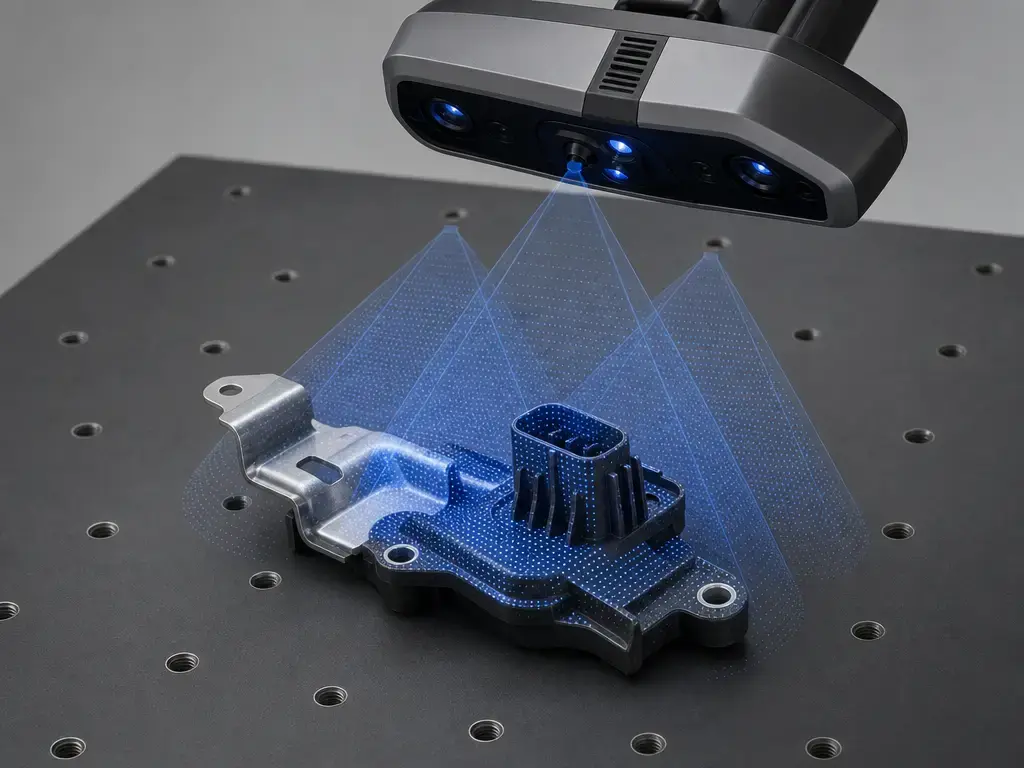
“Small-to-medium” only becomes useful once you translate it into scan geometry. Space Spider’s published working distance is 0.2–0.3 m, and its field of view runs from 90 × 70 mm at close range to 180 × 140 mm at the far end of that envelope. In shop terms, the scanner is happiest when you can keep the part close, keep features overlapping from pass to pass, and avoid turning one compact object into a large stitching project. [1] [2]
Once the part stretches beyond that close-range window, the key risk shifts from “can the scanner see the detail?” to “can the stitched data preserve the relationships that matter?” Space Spider’s scale-dependent term is published as up to 0.05 mm + 0.3 mm/m, which is useful context for longer spans but not a guarantee that a stitched larger part behaves like a single rigid metrology setup. NIST’s structured-light work is the caution here: error sources vary with configuration and with the real object, not just the nominal spec line. [1] [17]
Using the manufacturer formula purely as a derived example gives the following values. [1]
| Derived span | Formula result | Plain-language meaning |
|---|---|---|
| 0.1 m | 0.08 mm | Local feature spacing on a clip, tab, or boss. |
| 0.5 m | 0.20 mm | A stitched region on a bracket or housing. |
| 1.0 m | 0.35 mm | A much larger assembled area where alignment risk rises. |
These are arithmetic examples, not independent proof of whole-part fit. For mounting holes, mating faces, and registration features, minimizing stitching is usually more important than repeating the smallest brochure number. [1] [17]
Scan-to-CAD workflow for automotive parts (what’s native to Artec Studio vs what isn’t)
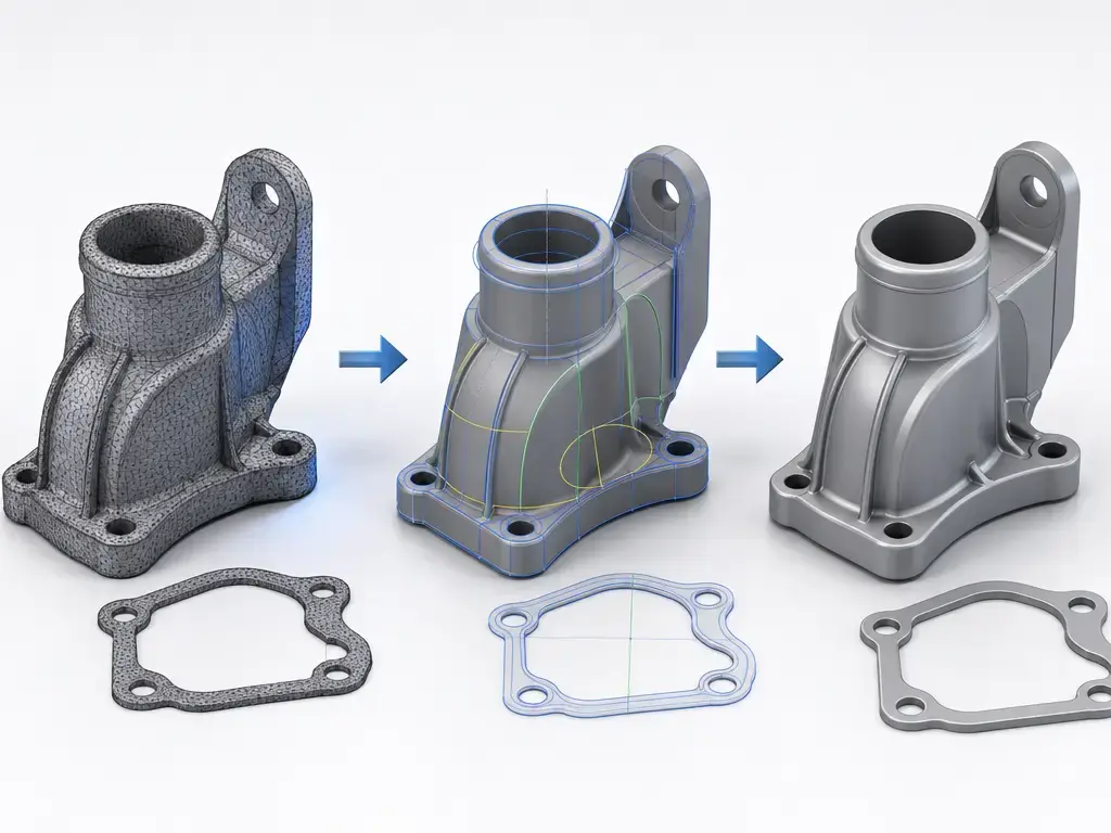
A practical artec space spider scan to cad workflow starts with the measurement question, not the scanner. Artec Studio positions its reverse-engineering tools around 2D profiles, primitive extraction, constraints, mesh-to-CAD surfacing, and export to SOLIDWORKS or Design X, while Leica’s reverse-engineering documentation describes the broader surfacing chain from mesh or point cloud to polylines, curves, and fitted NURBS or BSpline surfaces exported as IGES or STEP. [6] [22]
- Define the goal and tolerance, because a reference mesh, a repair surface, and a production CAD model are not the same deliverable. [22]
- Prep the surface only if needed, especially on shiny, transparent, or otherwise difficult parts. [8]
- Capture overlapping passes while staying inside the scanner’s intended envelope and keeping alignment stable. [1] [6]
- Register, fuse, and clean the scan data so the mesh represents the part rather than the environment around it. [6]
- Extract 2D profiles where section geometry actually carries design meaning. [6]
- Fit primitives only where the geometry is genuinely simple, such as cylinders, cones, spheres, planes, toruses, or boxes. [7]
- Build surfaces from the cleaned data or curve network, then export CAD-compatible formats such as IGES or STEP when appropriate. [7] [22]
- Validate the result against the scan and the physical part before trusting it for fit-sensitive work. [22]
The important limitation is that CAD-compatible export is not the same thing as automatic design-intent recovery. Artec Studio documentation states that an autosurface model can be exported to external CAD software as a CAD model, but feature logic, constraints, tolerances, and manufacturability decisions still sit with the user or with downstream CAD and reverse-engineering tools. [6] [7]
Reflective metal, glossy black plastic, glass: surface prep and its metrology cost
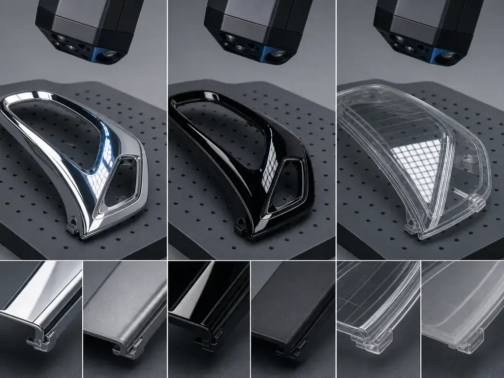
Optical scanners struggle when light reflects specularly, gets absorbed, or passes through the part instead of returning as a clean signal. That is why glossy black plastic, chrome-like trim, polished metal, and glass are common problem cases. Artec’s own support guidance says spray is seldom required thanks to the Sensitivity feature in Artec Studio, but adds that objects that are too shiny, too transparent, or otherwise difficult to capture may still need it. [8]
That prep has a measurement cost. AESUB Blue publishes a layer thickness of 8–15 μm, which is 0.008–0.015 mm, along with an effective scan time of about 1–2 hours and a sublimation time of about 4 hours. On a rough reverse-engineering job that may be acceptable, but in any sub-0.1 mm discussion it is not a free variable. [9]
The Car SOS center-console example is useful because it shows the tradeoff in context. In that manufacturer case study, AESUB Blue matting spray was used, and the part was prepared, scanned, and processed from captured data into a mesh and then a CAD model in Artec Studio within an hour, with additional modeling in Fusion 360 and about eight more hours of printing afterward. It is a practical workflow example, not an independent benchmark. [11]
Reverse engineering vs traceable inspection (standards boundary section)
Reverse engineering and traceable inspection answer different questions. Reverse engineering is usually about capturing geometry well enough to rebuild, modify, or reference a part. Traceable inspection is about verifying performance within a defined acceptance or reverification procedure, often with specific artifacts, conditions, and documentation. A small accuracy number on a brochure is not the same as a traceable acceptance test for your specific part and surface. ISO 10360-13:2021 is the relevant standards anchor because it specifies acceptance and reverification tests for optical 3D coordinate measuring systems when measuring lengths as stated by the manufacturer, and only when the surface characteristics are restricted and within a cooperative range. [14]
That standards context has also moved on from older VDI/VDE guidance. DIN EN ISO 10360-13:2023-11 is the current DIN/EN adoption of ISO 10360-13:2021, and DIN Media notes that the publisher recommends it in lieu of withdrawn VDI/VDE 2634 Blatt 2 and Blatt 3 documents. VDI/VDE 2634 Blatt 3:2008-12 is still useful historical context for how multi-view area-scanning systems were framed, but it is no longer the main current reference point. [15] [16]
Space Spider vs Spider II vs Eva (automotive reverse engineering fit)
All three Artec models discussed here are handheld structured-light scanners, but they sit in different working envelopes. Space Spider is the older close-range detail option, Spider II is the current close-range high-detail option, and Eva is the broader-coverage tool when part scale begins to overwhelm the small-part logic. [1] [3] [4]
| Scanner | Best-fit automotive use | Specs to cite | Boundary caveat |
|---|---|---|---|
| Space Spider | Small brackets, clips, trim details, worn local geometry | 0.05 mm accuracy; 0.1 mm resolution; 0.2–0.3 m working distance; 90 × 70 to 180 × 140 mm field of view. [1] | Still useful, but it is the discontinued model in this family and not the current high-detail Artec path. [1] [5] |
| Spider II | Close-range scan-to-CAD on small parts where finer detail and faster capture matter | 0.05 mm accuracy; 0.05 mm resolution; 30 fps; 8 mln points/s; 0.19–0.3 m working distance; 128 × 104 to 171 × 152 mm field of view. [3] | Better resolution and throughput do not remove the same close-range access limits. [3] |
| Eva | Larger components, broader reference capture, easier coverage planning | 0.1 mm accuracy; 0.2 mm resolution; 0.4–1 m working distance; 214 × 148 to 536 × 371 mm field of view; 61,000 cm³ capture zone. [4] | Easier on larger parts, but less suited to tiny local features than the close-range pair. [4] |
The simplest decision rule for artec eva vs artec space spider for reverse engineering is this: choose Space Spider or Spider II when the part is compact and the important geometry is local, and choose Eva when working distance, field of view, and reduced stitching matter more than the last bit of small-feature density. Spider II mainly changes the answer by being the newer close-range Artec option with finer published resolution and much faster throughput. [1] [3] [4]
When Space Spider is not the best 3D scanner for car parts
Space Spider is the wrong tool when the job is dominated by large smooth panels, awkward in-situ reach, whole-vehicle context, or surfaces that remain optically difficult even after reasonable prep. Its 0.2–0.3 m working distance and small field of view are helpful on compact detailed parts, but limiting under a car, across a door skin, or around large interior trim assemblies. If the real problem is hidden internal geometry, optical handheld scanning is simply the wrong modality; CT is a different tool class. [1] [8]
The alternative should be chosen by class, not by hype. Within Artec’s range, Spider II is the current close-range detail option and Eva is the better coverage option. Outside that family, laser or hybrid metrology systems are often chosen when reflective-surface behavior, inspection framing, or certification language matters more than handheld structured-light convenience. [3] [4] [20] [21]
Vendor automotive examples (useful, but not independent benchmarks)
Artec’s own automotive application page is useful as a scale illustration, not as proof of universal performance. It lists a radiator grille scanned with Leo in 7 minutes, a crankshaft in 8 minutes, a hubcap with Eva in 6 minutes, a carburetor with Space Spider in 30 minutes, and a semi-trailer truck with Ray II over 6 hours. The pattern reinforces the main point: scanner choice changes with scale and capture strategy. [10]
The same caution applies to manufacturer case studies. Ruffian Cars used Eva for the entire car and Space Spider for individual components, while the Ford Eifel restoration workflow used Eva for body, interior, and frame capture and ended with a point cloud, polygon model, and texture dataset. These examples are useful for understanding the split between broad coverage and small-part detail, but they are not independent accuracy benchmarks. [12] [13]
Verdict: the best 3d scanner for car parts depends on the part
For small detailed automotive parts, Space Spider remains technically credible, but it is not automatically the best 3d scanner for car parts. The manufacturer still lists up to 0.05 mm accuracy and 0.1 mm resolution, while current Artec Studio tech specs place it in the discontinued-model category rather than the current product line. [1] [5]
- Space Spider fits small detailed parts when close-range access is easy and you already have the scanner or a practical reason to use it. [1]
- Spider II is the current Artec choice when you want the same close-range logic with finer published resolution and much faster capture throughput. [3]
- Eva is the better fit when the job is growing into larger housings, broader trim sections, or vehicle-scale reference capture. [4]
- Laser or hybrid metrology class belongs in the conversation when reflective surfaces, inspection workflows, or certification language start to dominate the requirement. [20] [21]
Validation still sits downstream of scanning, regardless of which class you choose. [14] [22]
FAQ
Is Artec Space Spider good for scan to CAD?
Yes, if the part is small enough and the goal is realistic. Artec Studio’s reverse-engineering tools are positioned around 2D profiles, primitive extraction, constraints, mesh-to-CAD surfacing, and export to downstream tools such as SOLIDWORKS or Design X. That means it can support scan-to-CAD work well, but the result is still a reconstruction workflow rather than automatic recovery of original design intent. [6] [7]
Is Artec Space Spider the best 3d scanner for car parts?
Only for a narrow slice of the problem. It is strongest on small detailed parts that fit a close-range structured-light workflow, especially where feature density matters more than coverage. Once parts get larger, harder to access, or more inspection-driven, the answer changes quickly and the standards boundary matters more. [1] [14]
Artec Eva vs Artec Space Spider for reverse engineering: which to choose?
Use Space Spider when the critical geometry is local and compact, and use Eva when broader coverage and easier standoff matter more. The practical differences are Space Spider’s 0.2–0.3 m working distance and smaller field of view versus Eva’s 0.4–1 m working distance and much larger capture envelope. That makes Space Spider better on clips and brackets, and Eva easier on larger panels, housings, and vehicle reference areas. [1] [4]
How does Artec Spider II compare with Space Spider for automotive parts?
Spider II stays in the same close-range structured-light class but improves the published resolution from up to 0.1 mm to up to 0.05 mm and raises capture speed to up to 30 fps with up to 8 mln points/s. The main point is not that it changes scanner class, but that it is the newer close-range Artec option with more detail and throughput on paper. [1] [3]
Can Space Spider scan glossy black, chrome, or glass car parts?
Sometimes, but those are exactly the surfaces that often cause trouble for optical systems. Artec says spray is seldom required overall, yet shiny, transparent, or otherwise difficult objects may still need it. If you use a vanishing spray such as AESUB Blue, remember that the coating itself has a published thickness in the 8–15 μm range, so it becomes part of the measurement chain. [8] [9]
Does Artec Space Spider produce a CAD model automatically?
No. It can capture scan data, help you fit primitives or build autosurfaces, and export CAD-compatible outputs, but a usable engineering model still depends on decisions about sections, surfaces, constraints, and intended function. Leica’s reverse-engineering workflow description is a useful reminder that mesh or point cloud data often has to be turned into curves and then into fitted surfaces before it behaves like real CAD. [7] [22]
What standard applies if I want traceable accuracy claims from an optical 3D scanner?
ISO 10360-13:2021 is the core reference for acceptance and reverification testing of optical 3D coordinate measuring systems when measuring lengths as stated by the manufacturer, and it applies only within a cooperative surface range. For DIN/EN context, the current adoption is DIN EN ISO 10360-13:2023-11, which DIN Media recommends in lieu of withdrawn VDI/VDE 2634 Blatt 2 and Blatt 3 guidance. [14] [15]
Related on 3D Mag
- Artec Space Spider: the best 3D scanner for scan-to-CAD
- Artec Spider II: the best 3D scanner for prosthetics and orthotics
Sources
- Artec Space Spider product page — manufacturer page — undated; accessed 2026-07-28 — https://www.artec3d.com/portable-3d-scanners/old/spider
- Artec Space Spider brochure PDF — manufacturer PDF — SS-B-001-01/2023-EN-NOP — https://cdn.artec3d.com/content-hub-files/artec.s.spider-b-a.8-web-en-nop.pdf
- Artec Spider II product page — manufacturer page — undated; accessed 2026-07-28 — https://www.artec3d.com/portable-3d-scanners/artec-spider
- Artec Eva product page — manufacturer page — undated; accessed 2026-07-28 — https://www.artec3d.com/portable-3d-scanners/artec-eva
- Artec Studio tech specs — manufacturer page — undated; accessed 2026-07-28 — https://www.artec3d.com/3d-software/artec-studio/tech-specs
- Artec Studio reverse engineering page — manufacturer page — undated; accessed 2026-07-28 — https://www.artec3d.com/3d-software/artec-studio/reverse-engineering
- Artec Studio 19 docs: Working with CAD objects — official documentation — AS19; accessed 2026-07-28 — https://docs.artec3d.com/as/19/en/cad.html
- Artec Support: Scanning sprays — manufacturer support — updated 2023-08; accessed 2026-07-28 — https://support.artec3d.com/hc/en-us/articles/205338441-Scanning-sprays
- AESUB scanning sprays product page — manufacturer page — undated; accessed 2026-07-28 — https://aesub.com/products/3d-scanning-spray-cans/
- Artec automotive applications page — manufacturer page — undated; accessed 2026-07-28 — https://www.artec3d.com/3d-scanning-solutions/automotive
- Artec case study: Car SOS — manufacturer case study — 2021 context; accessed 2026-07-28 — https://www.artec3d.com/cases/car-sos
- Artec news/case study: Ruffian Cars — manufacturer news — 2021-03-01; accessed 2026-07-28 — https://www.artec3d.com/news/ruffian-cars
- Artec case study: 1937 Ford Eifel classic car — manufacturer case study — undated; accessed 2026-07-28 — https://www.artec3d.com/cases/3d-scanning-rare-classic-car
- ISO 10360-13:2021 official ISO page — standard listing — 2021-09; accessed 2026-07-28 — https://www.iso.org/standard/74957.html
- DIN EN ISO 10360-13:2023-11 listing — standard listing — 2023-11; accessed 2026-07-28 — https://www.dinmedia.de/en/standard/din-en-iso-10360-13/341772652
- VDI/VDE 2634 Blatt 3:2008-12 listing — standards listing — 2008-12; accessed 2026-07-28 — https://www.dinmedia.de/de/technische-regel/vdi-vde-2634-blatt-3/109737809
- NIST PDF: Sources of Errors in Structured Light 3D Scanners — government/scientific page — 2019 paper listing; accessed 2026-07-28 — https://tsapps.nist.gov/publication/get_pdf.cfm?pub_id=927473
- NIST AMS 100-39 PDF — government/scientific PDF — March 2021; accessed 2026-07-28 — https://nvlpubs.nist.gov/nistpubs/ams/NIST.AMS.100-39.pdf
- ASTM E2544-24 listing — standards listing — active; accessed 2026-07-28 — https://store.astm.org/e2544-24.html
- Creaform HandySCAN BLACK Elite technical specifications — manufacturer page — undated; accessed 2026-07-28 — https://www.creaform3d.com/en/products/portable-3d-scanners/portable-3d-scanner-handyscan-3d/technical-specifications
- SHINING 3D FreeScan Combo Series specs — manufacturer page — undated; accessed 2026-07-28 — https://www.shining3d.com/metrology-solutions/hybrid-light-source-metrology-3d-scanner/freescan-combo-series
- Leica Cyclone 3DR docs: Reverse engineering introduction — vendor documentation — 2025.2 docs; accessed 2026-07-28 — https://rcdocs.leica-geosystems.com/cyclone-3dr/2025.2/Introduction_1