
Summary
For 3D scanning for shipbuilding, Artec Jet is often a best fit when the job needs fast coverage, mobile capture, and mapping-level output rather than tight point-level verification. Artec lists Jet mapping accuracy as ±15 mm in general environments and ±10 mm in indoor or underground environments, so its headline accuracy should be read as a manufacturer mapping spec, not as a universal dimensional reference. [1]
Artec Ray II fits a different role in the same product line. Artec publishes Ray II 3D point accuracy as 1.9 mm at 10 m, 2.9 mm at 20 m, and 5.3 mm at 40 m, which makes it the stronger Artec option when tighter point accuracy, controlled scan-to-CAD work, or traceable dimensional checking matter more than pure coverage speed. The practical takeaway is conditional, not absolute: use Jet when coverage and mobility are the priority, and use Ray II or other metrology-oriented workflows when the task is driven by tighter point accuracy and validation requirements. [3] [7]
What this article is and is not claiming
This article makes a capability-based recommendation for the Artec Jet 3D scanner in marine vessel 3D scanning: it is useful when you need mobile coverage and mapping-level output, but not when the task demands inspection-grade dimensional traceability. This recommendation is capability-based: we did not find a reliable independent corpus of Artec Jet shipbuilding/refit case studies; Artec publishes a boat dataset example. [1]
Brochure specs ≠ shipyard performance; validate against control and task requirements. Artec’s public boat example is narrow evidence only: a large boat in dry storage, captured handheld in 3 minutes, producing a 260 MB LAZ dataset, with a listing date of May 25, 2026. Shipbuilding research also warns that measurement performance observed in the yard is systematically worse than datasheet performance. [1] [7]
This article does not claim underwater use, NDT replacement, or class-acceptance equivalence. It is meant to clarify when Jet is enough, when Artec Ray II is the better Artec-line choice, and when a different metrology workflow is still required. [1] [3]
One keyword, three very different marine jobs
Dry-dock exterior hull + topsides context
In dry dock, ship hull scanning usually means capturing the exterior shell, topsides, appendages, and major openings from stand-off positions, with enough visible geometry to keep the project registered. This is a marine vessel 3D scanning problem, but not a single one: the same hull scan may support retrofit context, collision checks, coating planning, or later modeling. Shipbuilding literature describes the physical scale clearly, with units around 3 to 5 m high and roughly 20 to 40 m on a side, and modules around 20 to 40 × 20 to 40 m with heights of 10 to 15 m. That scale naturally favors workflows that can cover distance and preserve coherence across broad surfaces. [7]
Onboard interiors for vessel refit/as-built
A vessel refit 3D scan inside accommodations, machinery spaces, corridors, or tanks is a different scenario. Occlusion is stronger, access is tighter, and long straight runs can be feature-poor. The goal is often as-built geometry for routing, clash checks, or space planning rather than a complete exterior shell. The tolerance context also changes the tool decision: shipbuilding tolerances are often a few millimetres, and the usual metrology rule of thumb is that measurement uncertainty should be about one order of magnitude smaller than the variability being checked. That is why the later examples in this article are labeled by scenario bucket, not just by the generic term “shipbuilding.” [7]
Fabrication/block/yard-scale dimensional quality management
The third bucket is fabrication, block assembly, and yard-scale dimensional quality management. Here the question is often whether parts, blocks, or assemblies fall within a defined tolerance window before they move downstream. That is a different measurement task from both exterior hull capture and onboard refit work. A scanner that is useful for broad context capture can still be the wrong tool for tolerance-driven verification, because the governing metric shifts from mapped scene consistency to tighter dimensional checking. In practice, scanner choice only becomes meaningful once the scenario is stated explicitly: dry-dock exterior context, onboard refit as-built, or fabrication and DQM. [7]
Why 3D scanning for shipbuilding is technically difficult
3D scanning for shipbuilding is difficult because the yard is not a controlled metrology lab. Exterior hulls can be wet, reflective, dark, or partially shadowed. Interiors can be cramped, repetitive, and occluded by piping, outfitting, and temporary structures. Hull-modeling research documented 20 scan positions in one project and reported that rain, insolation, and black surface absorption negatively affected results. Separate shipbuilding research adds the broader warning that field performance is systematically worse than datasheet performance. [8] [7]
If the job needs only coverage, context, and a mapped scene, a mobile SLAM LiDAR workflow may be appropriate. If it needs tighter dimensional traceability, the target metric changes, and so does the tool class. [1] [7]
Common failure modes in marine/shipyard scans
- Reflective or absorbing coatings, including black paint.
- Wet surfaces and condensation.
- Weather, including rain and insolation.
- Lighting variability across decks, bays, and interiors.
- Occlusion from scaffolding, piping, outfitting, or hull curvature.
- Long, feature-poor corridors, tanks, or repetitive structural bays.
- Registration drift across long paths or multi-session jobs.
These are task-and-environment problems, not an argument against any one product. In mobile workflows, long paths and repeated areas matter because the scan has to remain geometrically consistent while the operator moves through changing conditions. Feature-poor or highly repetitive scenes make registration harder, and multi-session jobs add another layer of uncertainty at the merge stage. That is why the later sections separate capture, registration, and validation instead of treating “scan done” as a single step. [8] [12]
What Artec Jet is and what it is not
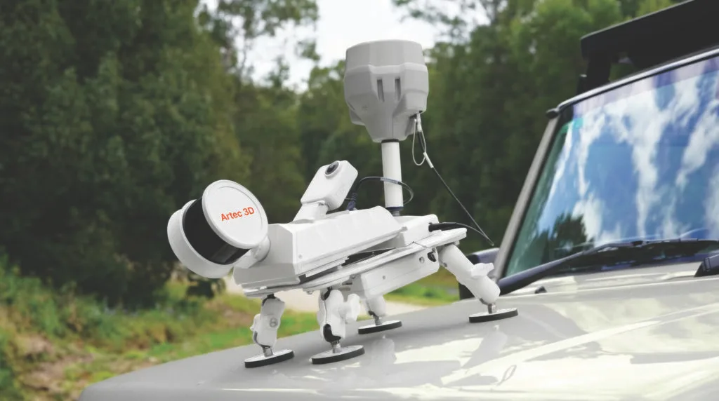
Artec Jet is a new scanner, launched on April 3, 2026. Artec positions it as a SLAM-based LiDAR mapping system, and the published drift figure of ±0.03% is a mapping-behavior metric, not a blanket point-accuracy claim. It should therefore be read as a mobile mapping tool, not as a structured-light handheld metrology scanner and not as a universal substitute for tighter inspection instruments. [2] [1]
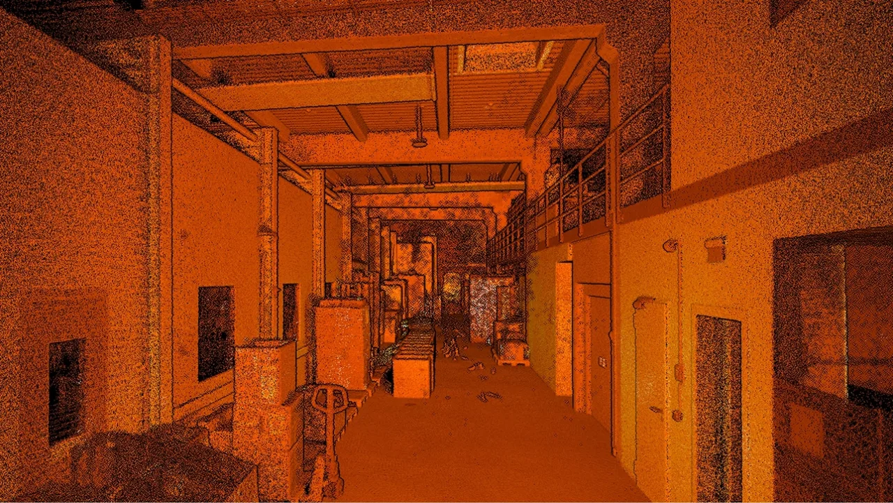
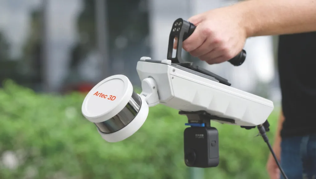
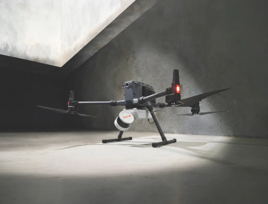
For shipyard use, the most relevant published specifications are tied to coverage, mobility, and field practicality: a 0.5 to 300 m sensing range, up to 640,000 points/s in single return and up to 1,920,000 points/s in triple return, a 360° × 290° field of view, Class 1 laser classification, IP65 protection, operation from -10°C to 45°C, 1.57 kg weight, and 512 GB of onboard storage for about 16 hours of data. Artec also lists handheld, backpack, drone, vehicle, cage, telescopic-pole, and robot deployment modes, plus LAS, LAZ, PLY, and E57 exports with full-resolution and decimated point clouds and a trajectory file. In practical terms, that makes Jet a mobile point-cloud capture platform for large scenes, not a one-device answer to every shipyard measurement problem. [1]
Is Artec Jet accurate enough for shipbuilding?
“Accurate enough” depends on the metric that governs the job. Mapping accuracy describes how well a mobile scan holds together as a scene. Point accuracy describes the accuracy of individual measured points relative to a reference. Point-to-point distance error concerns measured lengths between points. Registered-project accuracy is about how well scans or sessions align. Traceability means the result can be tied to a documented reference and uncertainty chain. Artec lists Jet mapping accuracy as ±15 mm in general environments and ±10 mm in indoor or underground environments, while Ray II publishes 3D point accuracy as 1.9 mm at 10 m, 2.9 mm at 20 m, and 5.3 mm at 40 m. These are not equivalent metrics and should not be compared as if they were the same thing. [1] [3]
That distinction matters in shipbuilding, where tolerances are often a few millimetres and the usual rule of thumb is that measurement uncertainty should be about one order of magnitude smaller than the variability being checked. A mobile SLAM workflow can be a good fit for layout context, clearance review, and as-built reference geometry, but it is a poor fit when the job is driven by tight point-level verification. ASTM E3125 matters here because it addresses point-to-point distance measurement performance for medium-range spherical-coordinate 3D imaging systems over roughly 2 m to 150 m, while also noting that real-world performance is affected by geometry, materials, and environment. [7] [4]
The practical rule is simple: start from the task metric, then choose the scanner. Jet’s drift figure should not be converted into a universal mm guarantee. Illustrative only, if 200 m × 0.03% is calculated literally, the arithmetic gives 60 mm, but that is not a promised field result and should not replace project validation. Artec also states that actual accuracy depends on environment geometry, scan duration, loop closures, and whether ground control points or RTK are used. [1]
| Use case | Metric that matters | Likely tool class | Control required? |
|---|---|---|---|
| Refit as-built for layout or clash context | Scene-level mapping with moderate dimensional confidence. [1] | Jet-class mobile SLAM LiDAR. [1] | Yes; use loop closures and fixed references when dimensional confidence matters. [1] [11] |
| Dry-dock exterior context plus yard coordinates | Broad geometry plus stable project coordinates. [1] | Jet-class mobile SLAM LiDAR. [1] | Yes; use ground control, check points, and coordinate checks across sessions. [1] [11] |
| Hull geometry for simulation inputs | Geometrically coherent surfaces with documented registration quality. [8] [9] | Jet-class mobile SLAM LiDAR with validation, or hybrid capture. [1] [8] | Yes; review residuals and independent checks before modeling. [4] [8] |
| Fabrication DQM and tolerance-driven checks | Few-millimetre dimensional verification. [7] | Ray II-class TLS or other metrology-oriented workflow. [3] [7] | Yes; independent verification and documented uncertainty are essential. [4] [7] |
| Formal acceptance, class, or NDT-driven inspection | Not LiDAR-only. [1] [7] | Dedicated inspection workflow. [7] | Yes; scan geometry alone does not satisfy the requirement. [1] [7] |
Control and registration strategy for vessel and refit jobs
For onboard interiors, treat the job as a control problem before it is a scanning problem. In GPS-denied spaces, Jet can still be useful, but long corridors, tanks, and repetitive bays make SLAM consistency harder to maintain. Artec documents georeferencing using ground control points, RTK data, or both, and independent mobile-laser evidence shows that control strategy materially affects the result. One study reported that 6 to 7 control points were the minimum needed in its test area to achieve the declared relative trajectory accuracy, while local accuracy improved up to about 10 control points with average spacing around 50 m when checked against a TLS reference. [1] [11]
For dry-dock exteriors with open sky, RTK can help tie the project to yard coordinates, but it does not remove the need for loop closures and check points. Independent SLAM evidence shows why: stationary tests in one study were under 0.020 m RMSE, while mobile tests revealed systematic errors and led the authors to recommend path strategies such as reverse-repetition. A scanner can therefore look better in a short, controlled test than in the moving workflow that actually matters on site. [12]
Control strategy rules of thumb by scenario
- Onboard interiors: prioritize loop closures, revisit anchors, and avoid long featureless runs; use targets or control when dimensional confidence is required.
- Dry-dock exteriors with open sky: consider RTK to reduce drift, but add ground control if you need stable project coordinates across days or teams.
- Multi-session or multi-mode projects: plan fixed references from the start, expect merge steps, and verify with check points before downstream modeling.
- Hybrid workflows: use fixed TLS data such as Ray II for the high-accuracy zones, then tie that data back to the mobile context scan.
In processing software, the practical question is not the brand name but whether the workflow preserves anchors, loop closures, and merge diagnostics well enough to support the task. For a vessel refit 3D scan, that may mean Jet for coverage plus fixed references for critical zones. For a higher-accuracy fabrication or hull area, it may mean using Jet only as contextual data and relying on tighter metrology for the regions that actually drive the tolerance decision. [1] [3] [12]
Artec Jet vs Artec Ray II for marine vessel 3D scanning
Jet and Ray II sit in different parts of the Artec line. Jet is a mobile SLAM LiDAR mapper, useful when you need coverage, mobility, and mapped context over large vessel areas. Ray II is a tripod-based terrestrial laser scanner, better suited when the task depends on tighter point accuracy and more controlled acquisition. Their published specifications are complementary, not interchangeable: Jet is published with mapping accuracy, while Ray II is published with distance-specific 3D point accuracy. [1] [3]
| Attribute / Metric type | Jet (mobile SLAM LiDAR) | Ray II (tripod TLS) | Best fit when… |
|---|---|---|---|
| Metric type not equivalent | Mapping accuracy. [1] | 3D point accuracy. [3] | You need to compare like with like, not mapping accuracy against point accuracy. |
| Accuracy figure | ±15 mm general; ±10 mm indoor/underground. [1] | 1.9 mm @ 10 m; 2.9 mm @ 20 m; 5.3 mm @ 40 m. [3] | The job is governed by tighter point-level geometry. |
| Range / coverage | 0.5–300 m. [1] | 0.5–130 m. [3] | You need broader mobile coverage versus fixed long-range detail capture. |
| Acquisition / resolution | Up to 640,000 pts/s single return; up to 1,920,000 pts/s triple return. [1] | Up to 2,000,000 pts/sec; 3 / 6 / 12 mm @ 10 m resolution settings. [3] | You are choosing between fast mobile mapping and controlled fixed-position detail. |
| Environmental rating | IP65; -10°C to 45°C. [1] | IP54; -5°C to +40°C, with extended low-temperature operation to -10°C only if internal temperature is at least -5°C at power-on. [3] | You need to weigh rugged mobile deployment against tighter fixed TLS capture. |
For marine vessel 3D scanning, the plain-language takeaway is straightforward: Jet is the mapper and Ray II is the tighter measurement tool. Jet is the better fit for rapid contextual capture, large dry-dock scenes, and refit work where the deliverable is a mapped reference. Ray II is the better fit when the deliverable depends on tighter point accuracy, traceable distance work, or a more controlled scan-to-CAD workflow. [1] [3]
What data you actually get and what you still have to build
Jet exports LAS, LAZ, PLY, and E57, along with a full-resolution point cloud, a decimated point cloud, and a trajectory file. That is the output stack you start with after capture. Jet exports point clouds; CAD/BIM models are downstream interpretations. For a vessel refit 3D scan, that distinction matters because the point cloud may be the evidence base, while the contractual or engineering deliverable may still be a simplified model, a mesh, a routed system model, or a set of extracted dimensions. [1]
| Deliverables stack (four levels) | What it is | Typical use in ship work | Built from |
|---|---|---|---|
| Raw or registered point cloud | Measured 3D points, not yet interpreted. [1] | Coverage review, reference geometry, completeness checks. [1] | Jet exports and trajectory data. [1] |
| Processed point cloud | Cleaned, aligned, decimated, or georeferenced points. [1] | Sectioning, filtering, navigation, engineering review. [1] | Raw or registered cloud. |
| Mesh or surface model | Surface representation built from the cloud. | Visualization, fitting, hull or interior surface work. [8] [9] | Processed point cloud. |
| Interpreted CAD/BIM or naval-architecture deliverables | Engineering model with dimensions, references, or design intent. | Retrofit design, as-built documentation, routing, renovation planning, or simulation workflows. [9] | Mesh or surface model plus manual interpretation. |
For ship hull scanning, the downstream purpose changes the model you need. One hull-scanning paper notes that the ship industry uses 3D hull models for renovation, as-built analysis, and simulations, among other reverse-engineering tasks. That means the same captured dataset may support very different outputs depending on whether the next step is visualization, hydrodynamic analysis, or engineering redesign. [9]
Standards and validation
ASTM E3125 is the standard to think about when you want a medium-range check on point-to-point distance measurement error. In plain English, it is about testing whether a spherical-coordinate 3D imaging system measures lengths the way you expect over roughly 2 m to 150 m. It also matters because the standard explicitly recognizes that real-world performance can shift with object geometry, surface reflectance, temperature, particulate matter, lighting, vibration, wind, and similar field factors. [4]
ASME B89.4.19-2021 is a different standard in a different context. In plain English, it prescribes performance-evaluation methods for laser-based spherical coordinate measurement systems, with emphasis on point-to-point length measurements, and it focuses specifically on laser trackers as industrial measurement tools rather than on general surveying or mobile mapping workflows. That makes it useful as a reference point for what rigorous large-volume metrology evaluation looks like, even though it is not a direct approval stamp for a mobile LiDAR shipyard workflow. [5]
NIST’s TLS review gives the broader framing. It describes terrestrial laser scanners as 3D imaging systems that acquire point clouds in spherical coordinates and argues that performance evaluation is necessary for reliability and metrological traceability. It also explains why manufacturer specifications are hard to compare cleanly without documentary standards. In shipyard terms, naming a standard is not enough; the workflow still needs control, independent checks, and a task-specific uncertainty argument. [6] [4]
Minimum validation plan before trusting scan-to-CAD dimensions
- Define the metric first: mapping accuracy, point accuracy, point-to-point length, surface deviation, or registration residual.
- Define the tolerance first: what deviation is actually acceptable for the vessel task.
- Establish control points or check points and an independent verification reference.
- Record environment constraints such as weather, reflectivity, lighting, vibration, and access limits.
- Capture overlap or loop closures and document registration residuals.
- Review whether the deliverable is a scan-derived model or a dimensionally controlled measurement result.
For ground control points, the main issue is not the label but the discipline. Fixed references reduce ambiguity when a point cloud becomes point-cloud-to-CAD input, and independent checks expose where the project is weaker than the brochure suggests. In shipyard work, that is often the difference between a useful as-built reference and a model that looks complete but cannot support the dimensioning task you actually need. [4] [5] [6]
Evidence from shipyards and hull-scanning research
What transfers from the literature is not a promise about Artec Jet specifically, but the operating context. Shipbuilding studies describe units around 3 to 5 m high and 20 to 40 m on a side, with modules around 20 to 40 × 20 to 40 m and 10 to 15 m high. They also describe tolerances that are generally a few millimetres and note that shipbuilding measurement performance in the field is systematically worse than datasheet performance. That is the real buying context for 3D scanning for shipbuilding: large structures, tight fit-up pressure, and imperfect conditions. [7]
Hull-scanning research adds the practical detail. One study used 20 scan positions and reported limitations from rain, insolation, and black surface absorption. The authors assumed point-cloud accuracy could reach about 1 cm, reported a standard deviation between the common set of points of about 0.03 m, and noted values reaching 3 cm in some hull regions. Another paper emphasizes that the ship industry uses hull models for renovation, as-built analysis, and simulations, which means capture quality affects downstream engineering. A 2024 Advanced Engineering Informatics result showing estimated measurement points within an allowable tolerance of 7 mm is useful as a workflow-specific DQM signal, but it should not be generalized into a universal shipbuilding tolerance rule. [8] [9] [10]
Limitations and hard boundaries
Geometry capture vs inspection vs class acceptance
Jet’s LiDAR can help capture visible geometry, and Artec lists LiDAR accuracy at ±10 mm together with change-detection capability at ±5 mm. These are useful figures for comparing mapped geometry and spotting larger differences in a documented scene. They are not the same thing as traceable inspection evidence. In shipbuilding, tolerances are often only a few millimetres, and the uncertainty target is usually much tighter than that, which is why geometry capture must not be confused with acceptance-grade verification. [1] [7]
- LiDAR captures visible geometry, not thickness, hidden corrosion, or cracks behind coatings.
- Mapping-level outputs are not automatically traceable inspection results.
- Underwater areas require different sensing methods.
Jet can support marine vessel 3D scanning and ship hull scanning workflows, but only within the boundary of the data it actually captures. A change-detection figure does not mean a marine component is cleared for acceptance, and a mapped surface does not mean hidden defects have been measured. [1] [7]
Conclusion
For 3D scanning for shipbuilding, Artec Jet is a best fit when the job needs mobile coverage, mapped context, and a workflow that can tolerate the manufacturer’s published mapping accuracy of ±15 mm in general environments or ±10 mm in indoor or underground environments. Use Artec Ray II or other instruments when the work is driven by tighter point accuracy, because Ray II’s published 3D point accuracy is 1.9 mm at 10 m, 2.9 mm at 20 m, and 5.3 mm at 40 m. In either case, the final decision still has to be validated against the actual task, because shipyard performance is systematically worse than datasheet performance. [1] [3] [7]
FAQ
Is Artec Jet accurate enough for 3D scanning for shipbuilding?
Sometimes, yes, but only when the governing metric is mapping-level scene capture rather than tight point-level verification. Artec lists Jet mapping accuracy as ±15 mm in general environments and ±10 mm in indoor or underground environments, which can be workable for coverage-first as-built or context capture. It is a weaker fit for few-millimetre DQM or inspection-style tasks. [1] [7]
Artec Jet vs Artec Ray II for ship hull scanning: which is better, and why aren’t the accuracy specs comparable?
Neither is universally better; they solve different problems. Jet publishes mapping accuracy, while Ray II publishes 3D point accuracy at stated distances: 1.9 mm at 10 m, 2.9 mm at 20 m, and 5.3 mm at 40 m. Those are different metric types, so the comparison only makes sense after you define whether the job is about mapped context or tighter point-level geometry. [1] [3]
Do I need ground control points or RTK with a SLAM LiDAR scan on a vessel?
If you need stable project coordinates or stronger dimensional confidence, yes, some form of control is usually warranted. Artec documents Jet workflows using ground control points, RTK data, or both, and independent MLS research shows that accuracy changes materially with control-point strategy. The need is strongest in long, repetitive, or multi-session vessel jobs. [1] [11]
What deliverables should a vessel refit 3D scan include?
At minimum, be clear about the stack: raw or registered point cloud, processed point cloud, mesh or surface model if needed, and interpreted CAD/BIM or naval-architecture output if that is the real deliverable. Jet itself exports point clouds and a trajectory file; the engineering model is still a downstream interpretation built for routing, clash checks, redesign, or analysis. [1] [9]
Expert: How should I validate point-to-point distance performance, and what is ASTM E3125 actually about?
ASTM E3125 is about evaluating point-to-point distance measurement performance for medium-range spherical-coordinate 3D imaging systems, roughly 2 m to 150 m. In practice, that means checking whether the system measures lengths correctly under conditions relevant to the project, while remembering that geometry, materials, reflectance, and environment can shift the result. [4]
Expert: What error budget changes when you merge TLS plus photogrammetry, or multiple scan sessions?
The merge becomes part of the measurement problem. In the cited hull-modeling study, the authors assumed point-cloud accuracy could reach about 1 cm, but the common-point-set standard deviation was about 0.03 m and some hull regions reached 3 cm. Multi-session or multi-sensor projects therefore need explicit registration checks rather than assuming each input accuracy simply carries through unchanged. [8]
Can LiDAR scanning replace hull thickness testing or class-required inspection?
No. LiDAR captures visible geometry. It does not measure thickness, hidden corrosion, or cracks behind coatings, and mapping-level outputs are not the same as traceable inspection evidence. That boundary is especially important in shipbuilding, where accepted dimensional uncertainty is often much tighter than a general geometry-capture workflow can support. [1] [7]
Related on 3D Mag
- Artec Jet: the best 3D scanner for industrial plants
- Artec Jet: the best 3D scanner for landscape and terrain surveying
- Artec Spider II: the best 3D scanner for prosthetics and orthotics
Sources
- Artec Jet product page — Manufacturer, accessed 2026-07-28.
- Artec Jet launch news — Manufacturer news, 2026-04-03, accessed 2026-07-28.
- Artec Ray II product page — Manufacturer, accessed 2026-07-28.
- ASTM E3125-17 listing — Standard listing, accessed 2026-07-28.
- ASME B89.4.19-2021 listing — Standard listing, accessed 2026-07-28.
- NIST / Measurement Science and Technology review on TLS performance evaluation — Official/scientific review, 2021, accessed 2026-07-28.
- Dimensional measurements in the shipbuilding industry: on-site comparison of a state-of-the-art laser tracker, total station and laser scanner — Scientific article, published 2022-10-29, accessed 2026-07-28.
- Combined Close Range Photogrammetry and Terrestrial Laser Scanning for Ship Hull Modelling — Scientific article, 2019-05-26, accessed 2026-07-28.
- Laser Scanning Ship Hulls to Support Hydrodynamic Simulations — Scientific article, online 2021-12-21, accessed 2026-07-28.
- Method for estimating management points for dimensional quality management in shipbuilding and offshore plant construction using terrestrial laser scanning and a computer-aided design model — Scientific article page, 2024, accessed 2026-07-28.
- Influence of Control Points Configuration on the Mobile Laser Scanning Accuracy — Scientific article, 2021-11-01, accessed 2026-07-28.
- Assessment of Slam Lidar – An Accuracy Assessment and Drift Anaylsis of the Leica BLK2GO — Scientific conference repository record, 2024-07-07, accessed 2026-07-28.