
Short answer: is Artec Jet the best fit for industrial plant as-built scanning?
Artec Jet is a strong fit for plant as-built scanning when the job calls for rapid, mobile, site-scale capture rather than the tightest possible metrology. It is a SLAM-based LiDAR mapping system, and its published figures — including 0.5–300 m sensing range, ±0.03% drift, multiple deployment modes, and mapping-oriented accuracy claims — support broad facility mapping more clearly than they support a universal precision promise. [1]
The key boundary is deliverable tolerance. When a project needs tighter control on critical geometry, a fixed-position terrestrial laser scanner such as Artec Ray II is usually the better fit within the same product family, because Ray II is specified with stationary TLS-style accuracy figures such as 1.9 mm at 10 m, 2.9 mm at 20 m, and 5.3 mm at 40 m. NIST’s review of TLS performance is a useful reminder that real application tolerances can range from a few tens of millimeters down to a few tens of micrometers. [3] [8]
What plant as-built scanning means in practical engineering terms
Plant as-built scanning means capturing the current physical geometry of an industrial site so engineers, maintenance teams, and document control can work from what is actually there rather than what legacy drawings say should be there. The usual output is a point cloud for facility documentation, measurement, verification, and scan-to-CAD work. The scan itself is not automatically a finished CAD or BIM model, and the tolerance target has to be set from the intended use of the deliverable. [8] [10] [11]
That distinction matters in brownfield plants, shutdown windows, and retrofit projects, where piping, steelwork, cable trays, and equipment often differ from record drawings. Point-cloud capture helps teams verify current geometry, plan modifications, and reduce field rework, but the engineering value depends on matching the capture method to the tolerance the downstream work actually needs. E57 matters here because it can store 3D point data, related attributes such as color or intensity, and 2D imagery, with standardized quantities expressed in SI units. [6] [8]
What Artec Jet is, and what problem it solves in plants
Artec Jet entered Artec’s lineup on April 3, 2026 as a SLAM-based LiDAR system for large-scale capture. In industrial plant scanning, it addresses a practical gap: teams often need more coverage than a small handheld scanner can comfortably provide, but they do not always have time to deploy a tripod-based TLS at every position during a shutdown or access-limited job. Jet is positioned around movement, coverage, and deployment flexibility across large facilities. [2] [1]
For plant work, its relevance comes from a mix of range, acquisition rate, field coverage, ruggedness, and export flexibility. Artec publishes a 0.5–300 m sensing range, up to 640,000 points/s in single return mode or up to 1,920,000 points/s in triple return mode, and a 360° × 290° field of view. The hardware is field-oriented: IP65 protection, -10 to 45 °C operation, 1.57 kg weight, 14–54 V at 64 W, 512 GB onboard storage, and about 16 hours of sensor data. It can be used in handheld, backpack, drone, vehicle, cage, telescopic pole, or robot configurations, and it exports LAS, LAZ, PLY, and E57, plus full-resolution and decimated point clouds and a trajectory file. [1]
Core Artec Jet plant-scanning use cases. [1]
- Plant as-built scanning
- Facility documentation
- Digital twin baseline capture
- Volumetric measurement
- Clash detection and retrofit planning
- Inspection access in difficult or unsafe areas
Metric glossary: what the numbers actually mean
3.1 Sensor-level metrics
Sensor-level metrics describe what the hardware can physically collect while scanning. Range, point rate, and field of view belong here, along with resolution or point spacing where the manufacturer publishes it. For Jet, headline figures such as 0.5–300 m range, up to 1,920,000 points/s, and a 360° × 290° field of view help with coverage planning and access strategy, but they do not by themselves prove that the final point cloud registration or scan-to-CAD output will satisfy a project tolerance. [1]
3.2 SLAM / trajectory metrics
SLAM metrics describe how well the system estimates its own path while moving. Drift, local or relative accuracy, revisit consistency, and loop closure belong in this category. Jet’s published ±0.03% drift figure is a trajectory-related manufacturer specification, not a universal statement about every measured object in every plant. That distinction matters because research literature shows that SLAM performance can vary substantially by system, method, and environment; one cited indoor study reported RMS errors ranging from 2.0 cm to 4.4 cm with one feature method and 1.7 cm to 4.7 cm with another across three different systems. [1] [9]
3.3 Deliverable-level metrics
Deliverable-level metrics determine whether the job is acceptable to engineering. Mapping accuracy, registration residuals, control-point agreement, checkpoint error, and downstream usability all belong here. Artec publishes Jet mapping figures of ±15 mm in general environments, ±10 mm indoors or underground, and ±5 mm for change detection capability, but those remain manufacturer-published workflow figures that still depend on geometry, route quality, loop closures, and QA. NIST’s tolerance context explains why direct comparisons across scanner classes can mislead: some jobs only need tens of millimeters, while others need much tighter control. [1] [8]
| Metric | What it means | Why it matters | Notes for Jet context |
|---|---|---|---|
| Mapping accuracy | How closely the mapped output matches reality in the intended workflow | Used for deliverable acceptance | Jet’s ±15 mm general and ±10 mm indoor/underground figures are manufacturer-published mapping claims, not universal acceptance values. [1] |
| Local / relative accuracy | How well nearby geometry lines up | Important for short runs and local features | Local agreement can look good even if global drift grows over a longer route. [9] |
| Drift | Trajectory error that accumulates as the scanner moves | Critical on long walks and incomplete loops | Artec publishes ±0.03% drift, but it is still a trajectory metric rather than a blanket object-accuracy promise. [1] |
| Change detection | Sensitivity to differences between capture states | Useful for monitoring and comparison work | Jet publishes a ±5 mm change-detection figure, but workflow and QA still determine whether that is usable on a real plant project. [1] |
| Range | Maximum useful sensing distance | Affects stand-off capture and access planning | Jet’s 0.5–300 m range supports site-scale capture planning. [1] |
| Point rate | Number of points collected per second | Affects coverage speed and density potential | High point rate helps coverage, but it does not guarantee better deliverable quality on its own. [1] |
| Resolution / point spacing | Sampling fineness on surfaces | Matters for detail visibility | Ray II publishes 3 / 6 / 12 mm selectable resolution at 10 m in a stationary TLS workflow, which is a different framing from continuous SLAM capture. [3] |
| Registration error | Misfit after aligning scans or trajectories | Directly affects engineering usability | Registration QA is often more important to downstream work than raw sensor throughput. [8] |
How SLAM LiDAR works for plant scanning
A SLAM LiDAR scanner builds a point cloud while simultaneously estimating its own position and orientation. The LiDAR sensor measures distances to surrounding surfaces, while the SLAM algorithm matches geometric features over time so the system can solve for motion and map together. When the route returns to an area that has already been seen, loop closure helps constrain the trajectory and reduce accumulated error. That makes continuous capture practical in corridors, structures, and work areas without stopping for a tripod setup at every station. [9]
Plant geometry can either help or hurt the SLAM solution. Pipe runs, structural steel, valves, handrails, walls, and floor edges give the system repeatable features to track. But repetitive pipe racks, long narrow corridors, and feature-poor zones such as open bays or plain walls can make different locations look too similar, which weakens localization. That is why a cloud can look dense and convincing in a local view while still carrying broader trajectory error across the full route. Project acceptance has to be based on measured QA rather than visual plausibility alone. [8] [9]
Real plants also add environmental disturbances. Moving people and equipment create transient geometry, steam and dust can interfere with returns, reflective insulation and transparent surfaces can reduce confidence in surface interpretation, vibration can disturb motion estimation, and occlusion can leave gaps that are only noticed later in processing. Published research already shows that SLAM outcomes vary across systems and methods even in controlled indoor comparisons, so plant work should assume even greater dependence on route planning, revisit strategy, and validation. [9] [5]
Verification and QA: how to know whether the scan is good enough
5.1 Control points, checkpoints, and georeferencing
Verification starts with the reference frame, not the scanner brand. Control points establish the coordinate system, checkpoints test whether the registered data actually lands where it should, and georeferencing ties the project to plant survey control when required. ASTM E3125 is useful background for thinking about point-to-point distance performance in medium-range laser-based 3D imaging systems, but it is not a direct mobile-SLAM acceptance recipe for plant projects. E57 matters after QA because it preserves interoperable point-cloud data and associated imagery or attributes for downstream use. [5] [6]
5.2 Loop closure, registration QA, and acceptance
Loop closure is one of the main checks on whether a moving capture route has remained self-consistent. After that, registration QA asks whether overlaps, checkpoints, and control alignment satisfy the project tolerance. Standards help with context but do not replace project judgment: ISO 10360-13 is a boundary reference for optical 3D coordinate measuring systems, not a direct certification path for mobile SLAM acceptance, and NIST’s tolerance discussion shows why acceptance must be driven by the application. For Jet specifically, the cited product material publishes mapping figures, but no reliable figure found for a formal acceptance test method in that material. [7] [8] [1]
QA checklist for plant as-built scanning. [1] [5] [8]
- Checkpoints confirmed against known reference points
- Control points established before capture
- RTK or survey control used where the project requires georeferencing
- Loop closures verified on return paths
- Project acceptance compared against tolerance, not just scan appearance
Plant as-built scanning workflow with Artec Jet
6.1 Plan
Start by defining the deliverable: a documentation cloud, retrofit model input, change-detection baseline, or archive record. Then define tolerance, control strategy, access limits, shutdown timing, and safety constraints. That front-end decision matters because Jet can be deployed in several ways, but not every deployment mode is appropriate for every unit, permit condition, or access route in a plant. A good route plan is part of data quality, not just logistics. [1]
6.2 Capture
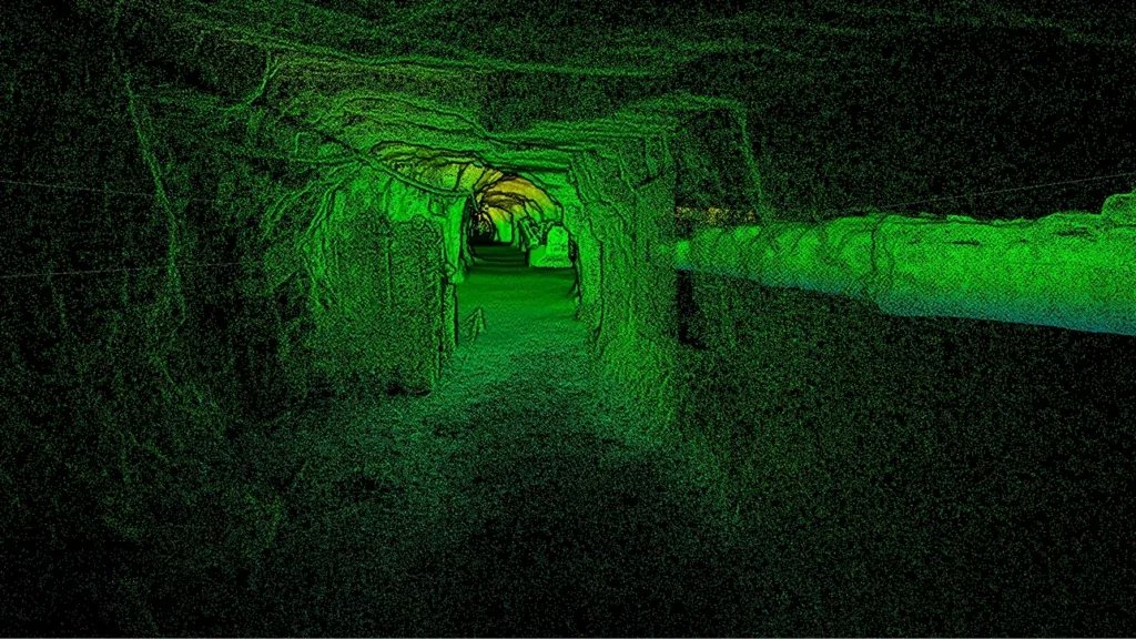
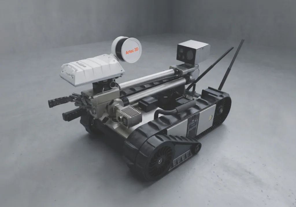
During capture, the practical goal is to preserve overlap, revisit key zones, and collect enough geometric context for later registration. Handheld, backpack, drone, vehicle, cage, telescopic pole, and robot deployment options are what make Jet relevant in stairs, yards, tunnels, elevated structures, and awkward spaces. Those options widen access, but they do not remove the operator’s responsibility to think about occlusion, movement, and loop closure while scanning. [1]
6.3 Process
Processing includes trajectory review, registration, outlier cleanup, georeferencing where needed, and deliverable QA. Jet’s outputs — LAS, LAZ, PLY, E57, full-resolution clouds, decimated clouds, and a trajectory file — support several downstream paths. Autodesk ReCap explicitly supports E57 import and export, while Autodesk’s AutoCAD support documentation says E57 point clouds are typically brought into AutoCAD by first importing and converting them in ReCap Pro to native RCP or RCS formats. [1] [10] [11]
6.4 Deliver
Delivery is not just file export. The handoff should state what the point cloud is intended to support and what tolerance or QA condition it passed. E57 export does not equal automatic CAD or BIM generation; the modeling step still requires interpretation, segmentation, and engineering judgment. In scan-to-CAD work, the point cloud is evidence and reference geometry, not a finished design model by default. [6] [10] [11]
Plant as-built scanning workflow.
- Define deliverable.
- Define tolerance and control strategy.
- Plan route, access, shutdown windows, and safety constraints.
- Capture with live coverage feedback.
- Process, register, georeference, QA.
- Export E57 / LAS / LAZ / PLY or convert through Autodesk workflows. [1] [10] [11]
- Model, measure, clash-check, or archive.
Artec Jet vs Artec Ray 3D scanner, Ray II, and other mobile scanners
The cleanest comparison is by role, not by spec-sheet ranking. Jet fills the mobile, site-scale capture role, while Ray II fills the stationary TLS role when a project needs more controlled, higher-detail geometry on critical plant features. Those roles can coexist on the same job: mobile capture for context and access-heavy coverage, fixed TLS for zones where tighter dimensional confidence matters. [1] [3] [8]
The phrase Artec Ray 3D scanner often points to the original Artec Ray naming, whose documentation describes a 1–110 m range and older baseline specifications. In current Artec-line plant comparisons, though, Ray II is the more relevant fixed-position reference. A compact handheld SLAM scanner can still be useful for small walk-throughs and local documentation, while wearable or backpack mobile mapping systems sit between handheld portability and site-scale reconnaissance. The right choice depends on deliverable tolerance, route length, and access pattern, not on a universal “best scanner” claim. [4] [3] [13] [9]
| Scanner class | Best plant role | Strength | Limitation |
|---|---|---|---|
| Artec Jet | Rapid site-scale plant capture | Broad coverage and multiple deployment modes. [1] | Not the best choice for fine-detail fixed metrology. [1] [8] |
| Artec Ray II / TLS | Higher-detail stationary plant scanning | TLS-style accuracy framing, selectable resolution, and fixed-position control. [3] | Requires setup time and multiple stations across a site. [3] |
| Compact handheld SLAM scanner | Small-zone walk-through capture | Very portable and easy to move through tight interiors. [13] | Less suited to long-range, site-scale plant coverage. [13] |
| Wearable/backpack mobile mapping | Repeated interior route capture | Hands-free mobility for extended walking routes. [9] | Still depends heavily on SLAM behavior, route quality, and later QA. [9] |
Where Artec Jet fits in industrial plants
Jet is most relevant when the plant problem is coverage and access rather than micro-detail. Brownfield retrofits, shutdown planning, and facility documentation often involve long routes, partial sight lines, overhead structures, and mixed indoor-outdoor conditions. In that setting, a mobile mapper can capture enough context quickly to support engineering decisions, while tighter fixed-position work is reserved for critical geometry. Jet’s published mobility limits — 60 km/h by vehicle, 5 m/s flight above ground, and 2 m/s flight underground — describe its operating envelope, but they should not be read as a promise that every plant can or should use every mode. [2] [1]
Its output and deployment options also fit the way plant projects move downstream. A job may need a fast documentation cloud first, then targeted modeling, clash review, or asset verification later. Collision-avoidance specifications and supported drone platforms matter in that discussion, but only within a site-specific planning and permissions framework. Public launch coverage did not publish a reliable public selling price, and Artec’s product path remains effectively a contact-sales workflow, so no reliable figure found for public price. [1] [12]
- Brownfield retrofit and revamp planning
- Pipe routing and clash detection
- Equipment replacement studies
- Facility management and asset documentation
- Maintenance planning and shutdown preparation
- Digital twin baseline capture
- Remote capture in difficult-access areas
Limitations, safety, and hazardous-area caution
Jet’s main technical limits are the ones common to mobile SLAM systems: drift, insufficient loop closure, repetitive geometry, feature-poor areas, and incomplete models caused by route choices or occlusion. A repetitive corridor of similar pipes may scan quickly yet still accumulate positional error over distance if the path does not provide enough distinctive structure or revisit opportunities. That is why a dense-looking cloud is not the same thing as a globally trustworthy plant-wide reference. [1] [9]
Environmental conditions can also reduce confidence. Reflective or transparent surfaces, dust, steam, moving people, moving equipment, vibration, and partial line-of-sight all complicate capture and later registration. None of that makes the tool unusable, but it does mean teams should expect more careful QA and, in some areas, supplementary fixed scans. ASTM E3125’s own significance section is a useful reminder that geometry, surface reflectance, particulate matter, vibration, temperature, and other real-world conditions can materially affect measured performance. [5] [9]
Safety needs a strict separation between ruggedness, remote access, and hazardous-location compliance. Jet’s IP65 rating and temperature range describe environmental durability, not explosion-proof certification. Its drone and collision-avoidance features can reduce exposure in difficult areas, but they do not make the system universally safe for every plant environment or any classified hazardous area. No reliable figure found in the cited product material for ATEX, IECEx, or explosion-proof suitability, so those claims should not be assumed. [1] [12]
Standards and interoperability context
Independent validation matters because scanner selection is tolerance-driven, not slogan-driven. NIST’s TLS review notes that application tolerances can range from a few tens of millimeters to a few tens of micrometers, which is why plant teams should start with the deliverable and then work backward to the capture method. Research on SLAM-based indoor mapping also shows measurable variation across systems and processing methods, reinforcing the point that a spec sheet is not a substitute for project-specific validation. [8] [9]
For interoperability, E57 is the strongest standards reference in this article because it defines a well-documented exchange format for 3D point data, attributes such as color or intensity, and 2D imagery, with standardized quantities in SI units. ASTM E3125 is useful only as a bounded reference for medium-range point-to-point performance evaluation, and ISO 10360-13 is a boundary reference for optical 3D coordinate measuring systems rather than a direct mobile-SLAM acceptance standard. In practice, clean exchange data and documented QA matter more than a bare export checkbox. [6] [5] [7]
Bottom line: when Artec Jet is the best fit
Artec Jet is the best fit for rapid, site-scale plant as-built capture when mobility, difficult access, and speed matter; it is not the universal answer for precision metrology or fine-detail inspection. Its strength is flexible SLAM-based coverage with manufacturer-published mapping figures, while Ray II remains the stronger Artec-line choice when the job shifts toward fixed-position, higher-detail TLS capture. The deciding factor is still the deliverable tolerance. [1] [3] [8]
FAQ
What is Artec Jet used for in industrial plants?
It is used for as-built scanning, facility documentation, retrofit planning, clash checking, change monitoring, and digital twin baseline capture. Its practical value is highest when teams need to move through a plant quickly without setting up a tripod at every position. The outputs are still point-cloud deliverables rather than finished models, but Jet can export E57, LAS, LAZ, PLY, and trajectory data for downstream engineering workflows. [1]
How does a SLAM LiDAR scanner work for plant scanning?
A SLAM LiDAR scanner measures distances with LiDAR while continuously estimating its own motion through the site. It builds the map and solves its position at the same time, then uses loop closures to reduce accumulated trajectory error when it revisits known areas. Plant geometry can help because it provides many surfaces to track, but repetitive pipe racks, steam, dust, and moving equipment can still reduce confidence in the global result. [9]
What is plant as-built scanning and why is it needed?
Plant as-built scanning creates a current-state point-cloud record of what is physically present in the facility. It is needed because brownfield plants often differ from legacy drawings, especially after maintenance changes, shutdown work, and retrofits. The point cloud supports verification, documentation, and scan-to-CAD workflows, but it does not automatically become a finished CAD or BIM model. Teams still have to interpret, model, and QA the output for the intended use. [6] [10] [11]
Artec Jet vs Artec Ray 3D scanner for industrial scanning: which is better?
Neither is universally better; the better choice depends on role. Jet is the stronger fit for rapid mobile coverage across large, access-heavy plant areas. Ray II is usually the stronger fit when the task needs fixed-position capture with tighter, more explicitly framed TLS accuracy on critical geometry. The older phrase Artec Ray 3D scanner often refers to the original Ray naming, but Ray II is the more relevant current comparison within the Artec line. [3] [4]
Expert-level: What tolerance band should a plant project set before choosing SLAM over TLS?
Start with the deliverable, not the scanner label. NIST’s review notes that TLS application tolerances can range from a few tens of millimeters down to a few tens of micrometers, which is a wide enough spread to make blanket recommendations meaningless. If the job can tolerate broader mapping error and needs speed, route coverage, and flexible access, SLAM may fit. If the job needs tighter geometric confidence, fixed-position TLS is the safer baseline. [8]
Expert-level: How do loop closures, control points, and checkpoints affect plant scan acceptance?
Loop closures test whether the moving trajectory remains self-consistent when the route returns to known geometry. Control points define the reference frame, and checkpoints test whether the registered cloud actually meets it. Without those controls, a cloud can look locally clean while still fail global acceptance. Jet’s cited product material publishes mapping figures, but no reliable figure found there for a formal acceptance test method, so project QA has to be defined at the project level. [1] [5] [8]
Does Artec Jet replace terrestrial laser scanning?
No. It fills a different role. Mobile SLAM capture is strong for reconnaissance, fast as-built documentation, and difficult-access routes, while terrestrial laser scanning remains the better starting point for higher-detail, fixed-position work. On many plant projects, the most robust workflow uses both: mobile capture for context and coverage, then stationary TLS for the parts of the site where tighter dimensional control matters. [3] [8]
Related on 3D Mag
- Artec Jet: the best 3D scanner for landscape and terrain surveying
- Artec Point: the best 3D scanner for turbine blade inspection
Sources
- [1] Artec Jet product page — manufacturer — https://www.artec3d.com/portable-3d-scanners/artec-jet
- [2] Artec Jet launch announcement — manufacturer news — https://www.artec3d.com/news/artec-jet-release
- [3] Artec Ray II product page — manufacturer — https://www.artec3d.com/portable-3d-scanners/laser-ray
- [4] Artec Ray documentation — official documentation — https://docs.artec3d.com/ray/
- [5] ASTM E3125-17 — standard — https://store.astm.org/e3125-17.html
- [6] ASTM E2807-11 / E57 — standard — https://store.astm.org/e2807-11.html
- [7] ISO 10360-13:2021 standard page — standard — https://www.iso.org/standard/74957.html
- [8] NIST review of terrestrial laser scanners — scientific / official research — https://www.nist.gov/publications/performance-evaluation-terrestrial-laser-scanners-review
- [9] Sensors 2018 SLAM accuracy study — scientific — https://doi.org/10.3390/s18103228
- [10] Autodesk ReCap supported file formats — official documentation — https://help.autodesk.com/view/RECAP/ENU/?contextId=supported_file_formats
- [11] Autodesk article: import E57 point cloud into AutoCAD — official documentation — https://www.autodesk.com/support/technical/article/caas/sfdcarticles/sfdcarticles/How-to-import-a-e57-Point-Cloud-into-AutoCAD.html
- [12] All3DP launch article on Artec Jet — industry publication — https://all3dp.com/4/artecs-new-jet-3d-scanner-digitizes-entire-sites-via-drone-mounted-or-handheld-lidar/
- [13] Leica BLK2GO technology page — manufacturer — https://shop.leica-geosystems.com/reality-capture/blk2go/technology