
Editor’s note (September 2026): On August 5, 2026, Artec 3D released Artec Point II, which replaces Artec Point in the company’s metrology lineup. Point II keeps the certified 0.02 mm accuracy and the target-based workflow described below, but captures up to 5.8 million points per second, more than double the original, with 54 laser lines in ultra-fast mode, 17 parallel lines in hyperfine mode, and a single-laser mode for deep holes. Specifications and quotes below refer to the original Artec Point; read our Point II launch coverage for the current model.
Summary: Turbine Blade 3D Scanning with Artec Point
Artec Point is a strong portable candidate for turbine blade 3D scanning when the job is external geometry capture, edge-detail documentation, and CAD comparison on blades, vanes, blisks, or similar aerofoil parts, and when a target-based workflow is acceptable. The manufacturer lists Artec Point as a handheld blue-laser scanner with up to 0.02 mm 3D point accuracy, up to 0.02 mm resolution, and scale-dependent volumetric accuracy of 0.015 mm + 0.035 mm/m, or 0.015 mm + 0.015 mm/m with the Artec Metrology Kit. Artec also states that Point is a target 3D scanner and that users need to attach targets for best results. [1]
It is not a universal replacement for CMMs, CT, ultrasonic testing, borescope inspection, or other NDT methods across all blade tasks. A 2026 hybrid rotor study found CMM expanded uncertainty U95 of about 4–6 µm on bores and optical scanning U95 of about 12–18 µm on freeform blade regions, supporting complementary rather than interchangeable use. Blade damage is also broader than surface geometry alone, with four main categories identified as surface damage, wear, material separation, and material deformation. [7] [9]
Start with the inspection objective: screening, documentation, or acceptance metrology
In blade inspection, the system class should follow the inspection objective more than the scanner brand. For screening and documentation, a portable optical system may be sufficient to record external geometry, edge wear, and as-found condition. For reverse engineering, dense surface capture often matters more than strict datum traceability. For acceptance metrology, the standard is higher because the workflow must hold datums, uncertainty, repeatability, and reporting together in a way that supports dimensional decisions. That task-first split is central to aerofoil metrology. [5] [7]
The shift from human visual inspection and sparse contact checks toward dense optical capture has improved coverage, but it has not made all methods equivalent. A 2022 study reported human inspection accuracy of 76.2% for screen-based piece-part inspection, 84.0% when inspectors had physical and tactile access to the blade, and 63.8% in borescope situations. A 2019 defect taxonomy grouped blade damage into four main categories: surface damage, wear, material separation, and material deformation. A 2026 hybrid study then showed why dense scanning and datum probing should not be treated as the same measurement mode, with CMM U95 of about 4–6 µm on bores versus optical scanning U95 of about 12–18 µm on freeform blade regions under controlled conditions. [10] [9] [7]
A separate 2024 compressor-blade fringe-projection study reported average chord-length deviation of 0.064 mm, maximum absolute deviation of 0.092 mm, and about 10 minutes for a multi-view measurement. Those figures are useful context for documentation, comparison, and many reverse-engineering workflows, but they do not by themselves justify acceptance decisions on a different scanner, blade size, or tolerance stack. ISO 10360-13:2021 specifies acceptance and reverification tests for optical 3D CMS length-measurement performance, while ISO/IEC 17025:2017 addresses laboratory competence rather than blade tolerance limits. [8] [5] [4]
A practical selector is:
- Choose handheld laser scanning when the goal is portable external geometry capture.
- Choose a dedicated airfoil cell when throughput and automation dominate.
- Choose CMM when datum traceability and bores/form are critical.
- Choose CT/NDT when internal defects must be found.
Why turbine blades and aerofoils are hard to scan
Turbine blades are difficult optical targets because the geometry changes quickly over a small volume. The airfoil is thin and twisted, the leading and trailing edges are narrow, and the root and platform add fillets, grooves, slots, and abrupt transitions. Reflective metallic surfaces, coatings, and repaired areas can also destabilize optical capture if the setup is not controlled. A blade inspection scanner therefore has to balance access, line of sight, feature size, and surface behavior at the same time. Visible blade damage further complicates inspection because it spans four main categories: surface damage, wear, material separation, and material deformation. [9]
Production-oriented airfoil systems show how specialized this problem can become. ZEISS lists measuring areas from 100 × 70 mm² and a 530 mm working distance for ATOS 5 for Airfoil, along with published workflow context of less than 20 minutes for fan blades and about 1 hour for blisks. That is a very different assumption set from a portable handheld inspection job around a root corner, repair blend, or awkward fixture. [11]
Typical blade inspection targets in published workflows include the following. [8] [11]
- CAD-to-scan surface deviation
- leading-edge and trailing-edge profile checks
- maximum thickness and section profile checks
- root and platform geometry checks
- dent, nick, scratch, erosion, and deformation documentation
- repair stock/removal planning
- reverse engineering or legacy digitization
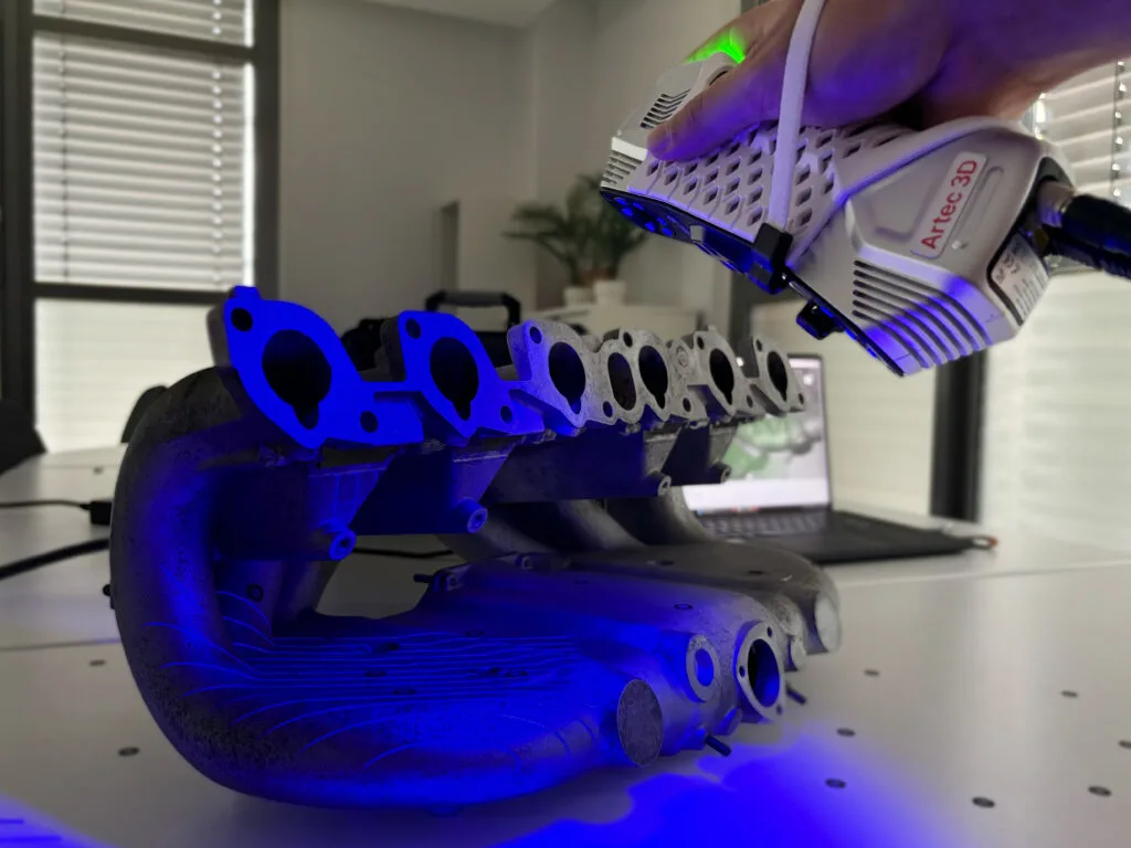
Artec Point specs that matter for aerofoil metrology
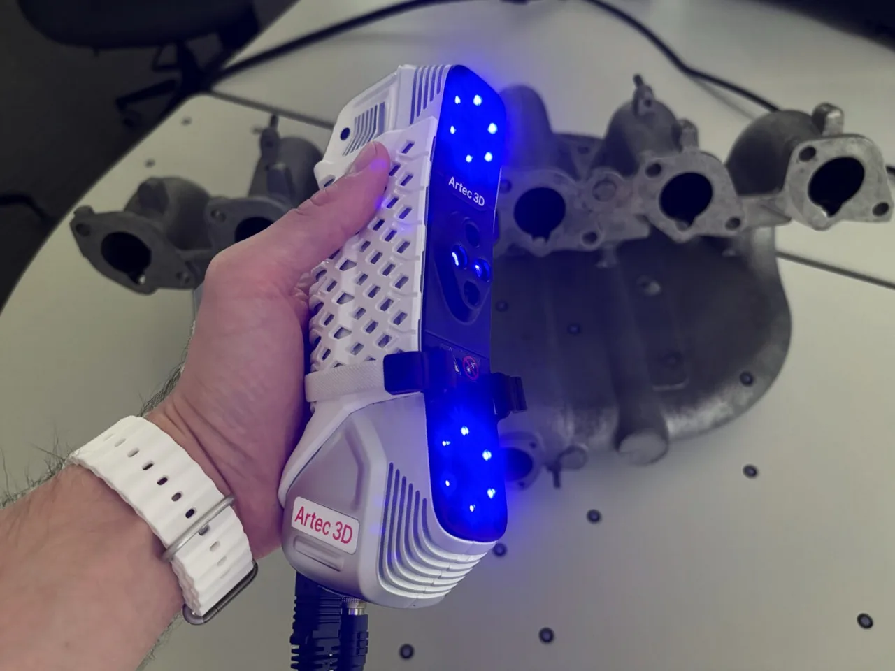
The Artec Point 3D scanner is a handheld, target-based blue-laser system, so the most relevant published figures for blade work are not just headline accuracy, but also volumetric behavior over distance, working envelope, scan modes, and how the tracking method fits a thin reflective part. Artec lists Point as a handheld scanner with a Class II blue-laser source and states that it is a target 3D scanner, meaning targets are required for best results. [1]
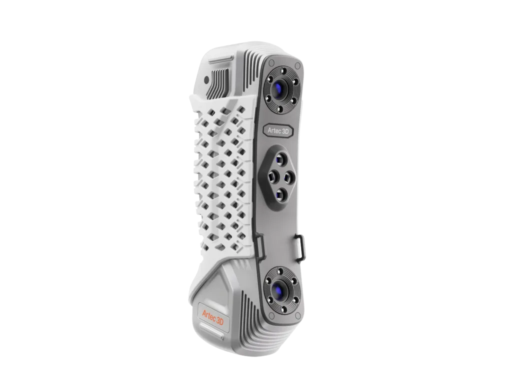
On the official product page, manufacturer-stated 3D point accuracy and resolution are both listed as up to 0.02 mm. Volumetric accuracy is listed as up to 0.015 mm + 0.035 mm/m, or 0.015 mm + 0.015 mm/m with the Artec Metrology Kit. The same page lists up to 2.8 million measurements per second, up to 120 FPS, a working distance of more than 300 mm, linear field of view up to 700 × 600 mm at the furthest range, and 550 mm depth of field. Scan modes are published as 17 crossed blue lasers for ultra-fast scanning, 7 parallel blue laser lines for hyper-fine scanning, and 1 single blue laser line for deep-hole scanning. Hardware figures include 0.57 kg weight, 203 × 80 × 44 mm dimensions, and IP50 dust protection. Those values are useful for estimating access, coverage, and scale behavior on blade workflows, but they do not by themselves prove acceptance-ready uncertainty on a real part. [1]
For software, Artec highlights 3D Compare Map, Tolerance Checking, sectioning, CAD-body creation through auto-surfacing, and one-click export to Control X. Those functions are relevant to inspection reporting and CAD comparison, but they are software capabilities, not independent proof of measurement validity. On accreditation language, the public product page states “ISO 17025 accredited based on VDI/VDE 2634 & JJF 1951,” and the launch press release says the scanner was verified in an ISO-certified lab against VDI/VDE 2634 and JJF 1951 standards. No reliable figure found for the exact public scope, VDI/VDE part, or JJF configuration beyond that wording. [1] [3]
Turbine Blade 3D Scanning Accuracy and Uncertainty
In turbine blade 3D scanning, brochure specifications describe scanner capability under defined conditions, not the uncertainty of a complete blade inspection. Here, accuracy means closeness to a reference, precision or repeatability means consistency across repeated captures, and resolution means the smallest separable detail or point spacing the system can represent. Those terms are related, but they are not interchangeable, and none of them alone determines whether a blade result is suitable for acceptance. [1] [2] [5]
Task uncertainty changes with reflective finish, alignment strategy, target layout, fixturing, environmental control, and feature class. The 2026 hybrid rotor study was run at 20 ± 0.5 °C, relative humidity below 50%, and with at least 2 hours of conditioning before measurement. Under those controlled conditions, CMM bores produced U95 of about 4–6 µm, while optical scanning on freeform blade regions produced U95 of about 12–18 µm. Separately, the 2024 multi-view fringe-projection blade study reported average chord-length deviation of 0.064 mm, maximum absolute deviation of 0.092 mm, and total multi-view measurement time of about 10 minutes. These numbers are useful context, but they are still setup-specific and should not be transferred directly to Artec Point or to every blade feature. [7] [8]
Terms that must not be confused:
- Accuracy ≠ resolution
- Precision/repeatability ≠ accuracy
- Point cloud ≠ mesh
- Mesh ≠ parametric CAD
- CAD comparison ≠ automatic pass/fail
- Surface scan ≠ internal NDT
- Manufacturer spec ≠ task-specific uncertainty
ISO/IEC 17025:2017 is about competence, impartiality, and consistent operation in testing and calibration laboratories. ISO 10360-13:2021 specifies acceptance and reverification tests for optical 3D CMS length-measurement performance, and its own scope notes that applicability depends on defined conditions and cooperative surface characteristics. VDI/VDE 2634 Blatt 1 provides triangulation-system context, not blanket validation for every blade workflow. The practical rule is to validate the method on representative blades, features, datums, and tolerance stacks before treating the result as inspection evidence. [4] [5] [6] [7]
Workflow: surface prep, targets, alignment, and reporting
A practical blade workflow starts with the part surface and the inspection objective. Reflective alloys, coatings, oxidation, oil, and repair patches can all change optical behavior, so the surface condition should be documented before capture. If no independent source confirms no-spray performance on representative blade finishes, surface treatment may still be required depending on finish and reflectivity. Controlled conditions matter as well: the 2026 hybrid study used 20 ± 0.5 °C, relative humidity below 50%, and at least 2 hours of conditioning, which is a reminder that shop-floor conditions can shift the result. [7]
Artec Point turbine blade inspection is inherently target-based, so target placement on the blade, fixture, or a surrounding frame has to preserve visibility around the full part envelope without obscuring critical geometry. The published scan modes also imply a feature-based strategy: 17 crossed blue lasers for broad capture, 7 parallel blue laser lines for finer geometry, and 1 single blue laser line for deep grooves or holes. In Artec Studio, 3D Compare Map, Tolerance Checking, sectioning, CAD-body creation, and export to Control X belong to the capture-and-analysis path, but they do not replace the metrology method behind the claim. Alignment should be chosen against CAD, a master part, or functional datums depending on whether the job is documentation, reverse engineering, or inspection against defined criteria. [1]
A practical Artec Point turbine blade inspection workflow looks like this. [1] [7]
- Define blade, datums, and acceptance criteria
- Clean or document the surface condition
- Decide target placement on blade, fixture, or surrounding frame
- Calibrate or verify scanner before inspection
- Capture broad geometry with fast/grid mode
- Capture edges, roots, grooves, or suspected defects with fine/single-line modes
- Register scans and build point cloud/mesh
- Align to CAD, master part, or functional datums
- Inspect sections, thickness, edge geometry, and deviation maps
- Export report with settings, tolerances, and traceability notes
The final report should state what was directly measured, how the alignment was performed, what settings were used, and which outputs are external-geometry evidence versus derived analysis. That distinction matters because a color map or section plot is evidence within a method, not a pass/fail decision by itself. [1] [5] [7]
Where Artec Point fits in blade quality control
Artec Point fits best where the inspection question is external geometry and the part can be handled with a target-based workflow. Its published up to 0.02 mm 3D point accuracy and scale-dependent volumetric accuracy make it relevant for incoming inspection, in-process verification, repair documentation, reverse engineering, fixture checks, and supplier comparison on small-to-medium blade parts. The practical attraction is portability plus dense surface capture, not a claim that one scan replaces every other blade method. [1]
Artec Point turbine blade inspection also makes sense when the reporting path includes CAD comparison, sections, and archived geometry for traceability. Artec Studio supports 3D Compare Map, Tolerance Checking, sectioning, CAD-body creation, and export to Control X, which is useful for documented external-geometry evidence. But the visible surface is still only part of the blade condition, because the defect taxonomy also includes material separation and material deformation that may require other methods to interpret fully. [1] [9]
Typical use cases include the following. [1] [9]
- CAD-to-scan deviation maps
- aerofoil section comparison
- edge nick/dent documentation
- root/platform geometry capture
- repair planning before blend-out or coating
- legacy blade reverse engineering
- supplier inspection record generation
When Artec Point is not enough
Optical scanning is limited to external geometry and surface-visible change. It can document material loss, dents, edge damage, erosion, blend areas, and deformation that are expressed in surface form, but it does not inherently detect internal cracks, cooling-channel flaws, hidden separation, or metallurgical damage. That limitation matters because blade damage includes four main categories, and not every category is fully observable in exterior geometry data alone. ISO 10360-13:2021 also does not turn an optical system into a universal solution for every blade feature; it specifies test frameworks for optical 3D CMS performance under defined conditions. [9] [5]
The gap becomes more obvious in datum-heavy acceptance, very tight bores, and regions with poor line of sight. In the 2026 hybrid study, CMM probing was better suited to bore-based measurements, with U95 around 4–6 µm, while optical scanning on freeform blade regions was about 12–18 µm. Longer blades, large fixtures, or multi-setup jobs also make scale accumulation more important because Artec Point’s published volumetric behavior is distance-dependent. Human inspection data is still useful context, but the variability of 76.2%, 84.0%, and 63.8% by access mode is a reminder to document methods rather than rely on informal judgment alone. [7] [1] [10]
The safest technical recommendation is usually hybrid inspection. Use optical scanning for external geometry, edge condition, section analysis, and deviation mapping, then use CMMs, borescopes, CT, ultrasonic testing, or thermography when the question includes hidden damage, internal structure, or datum-critical acceptance. That split respects both the strengths of full-field optical capture and the limits shown by standards and uncertainty studies. [7] [5]
Research and market context
Recent research supports a combined-method view rather than a replacement story. The 2026 hybrid rotor study showed that tactile CMM probing and optical scanning serve different measurands well, with the former stronger on bore-based datum verification and the latter stronger on dense blade-surface coverage. The 2024 fringe-projection study adds a second point of reference by showing average chord-length deviation of 0.064 mm, maximum absolute deviation of 0.092 mm, and total multi-view measurement time of about 10 minutes on a compressor-blade workflow. Together, those studies suggest that turbine blade inspection quality depends as much on fixturing, alignment, and interpretation as on sensor choice. [7] [8]
Market positioning follows the same split. Dedicated airfoil systems emphasize throughput and repeatable production workflows, while portable handheld systems compete on families of metrics such as accuracy, volumetric accuracy, resolution, speed, laser lines, and mass that are not always defined identically across vendors. Human visual inspection remains variable enough to keep objective, documented geometry capture relevant. Industry commentary published on April 11, 2025, also shows continued interest in automation, real-time monitoring, and AI-driven analysis around metrology, but that is market context only, not validation data for blade inspection or quality control. [11] [12] [10] [14]
Bottom line: is Artec Point the best choice for turbine blade 3D scanning?
Artec Point can be a best fit for portable external blade geometry inspection when the workflow is validated on representative parts, surfaces, datums, and tolerance stacks. Its published up to 0.02 mm 3D point accuracy, scale-dependent volumetric accuracy, and multiple laser modes make it a credible option for documentation, reverse engineering, incoming inspection, and repair-focused comparison work. But it remains a target-based system, and published manufacturer numbers should not be confused with task-specific uncertainty on an actual blade. Hybrid evidence still supports keeping CMM datum verification and optical freeform mapping as complementary methods. [1] [7] [5]
The accreditation wording also needs a careful read. Artec’s public materials state ISO 17025 accredited or ISO-certified-lab verification based on VDI/VDE 2634 and JJF 1951, but no reliable figure found for the exact public scope, VDI/VDE part, or JJF configuration beyond that wording. If you validate the method on your real parts and reporting path, Artec Point can be a strong choice for turbine blade 3D scanning. [1] [3]
FAQ
1. Is Artec Point suitable for turbine blade 3D scanning?
Yes, if the task is external geometry capture, CAD comparison, edge-detail documentation, or reverse engineering on a blade that can support a target-based workflow. The manufacturer lists up to 0.02 mm 3D point accuracy, but that figure still needs task-level validation on the actual part, surface, and tolerance stack. [1]
2. What makes a good blade inspection scanner?
A good blade inspection scanner needs enough measurement capability for the feature class, stable tracking, workable access to edges and roots, appropriate software for comparison and reporting, and a documented uncertainty path. In practice, workflow discipline matters as much as scanner specification. [1] [5] [7]
3. Is Artec Point the best aerofoil metrology scanner?
Only conditionally. It may be a strong portable choice for small-to-medium external blade geometry, but a dedicated airfoil cell can be better for throughput and automation, and a CMM can be better for datum-critical bores and form verification. “Best” depends on the inspection objective, not the brochure headline. [1] [11] [7]
4. Does Artec Point turbine blade inspection require targets?
Yes. Artec’s own product page says Point is a target 3D scanner and that users need to attach targets to objects for best results. On blades, that affects fixturing, visibility, and which areas can be scanned without covering critical features. [1]
5. Can turbine blade 3D scanning replace a CMM?
Not universally. The 2026 hybrid study found CMM U95 of about 4–6 µm on bores and optical scanning U95 of about 12–18 µm on freeform blade regions, which supports hybrid use rather than blanket replacement. Dense freeform data and traceable datum probing solve different inspection problems. [7]
6. Can a blade inspection scanner find cracks or internal defects?
Only if the defect is already expressed as a visible surface-geometry change such as an open chip, dent, or deformation. Optical scanning does not inherently detect internal cracks, cooling-channel defects, or metallurgical damage, so CT, ultrasonic testing, borescope inspection, or other NDT may still be required. [9] [5]
7. What is the difference between accuracy and resolution in turbine blade 3D scanning?
Accuracy is closeness to a reference, while resolution is the smallest separable detail or point spacing the system can represent. A scan can be high resolution yet still be inaccurate if calibration, alignment, fixturing, or surface behavior are poor. [2] [7]
Related on 3D Mag
- Artec Micro II vs Artec Point: Best 3D Scanner for Jewelry Precision and Portability
- Artec Point: the best 3D scanner for quality control
Sources
- Artec Point official product page
- Artec accuracy, precision, and resolution explainer
- Artec Point press release
- ISO/IEC 17025:2017 official ISO page
- ISO 10360-13:2021 official ISO page
- VDI/VDE 2634 Blatt 1 page
- Dumitrache et al., Metrology, 2026
- Chen et al., Sensors, 2024
- Aust and Pons, Aerospace, 2019
- Aust and Pons, Applied Sciences, 2022
- ZEISS ATOS 5 for Airfoil official page
- Creaform HandySCAN BLACK technical specifications
- FARO Quantum Max product specifications
- TCT Magazine, 2025