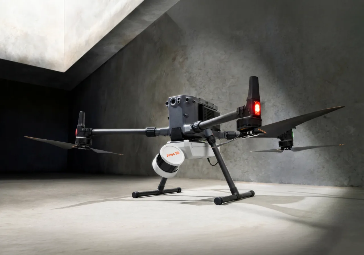

Summary: Is the Artec Jet 3D scanner a good fit for terrain surveying?
The Artec Jet 3D scanner is a mobile, SLAM-based LiDAR mapping system, so it belongs in the mobile mapping category rather than the tripod terrestrial laser scanning category. Local consistency is not the same as absolute georeferenced accuracy. Jet is also a recent product, with Artec’s launch announcement dated April 3, 2026. [1] [2]
That makes Jet a conditional fit, not a default “best” choice. It is strongest when a project values mobility, route flexibility, fast coverage, and efficient point-cloud capture over station-by-station setup. It is weaker when the deliverable must prove absolute placement in a project coordinate reference system, hold up to checkpoint review, or satisfy a documentation-heavy acceptance framework. Artec itself says actual accuracy depends on environment geometry, scan duration, loop closures, and whether ground control points or RTK are used, which is why terrain jobs should separate capture convenience from validation burden. [1]
Who it’s for / who it’s not for
Jet fits best when the main problem is collecting a topographic 3D scan quickly across a large or awkward site. That includes corridor-style mapping, industrial campuses, tunnels, mixed indoor-outdoor routes, GNSS-denied areas, and change-monitoring jobs where relative repeatability matters as much as, or more than, tightly documented absolute control. Artec’s own caveat matters here: actual accuracy depends on environment geometry, scan duration, loop closures, and whether GCPs or RTK are used. [1]
It is a weaker fit when the deliverable is tied to contractual acceptance, legal sign-off, or a workflow that must document control and checkpoints in a survey-style QA package. Open terrain with weak geometry, dense vegetation that hides the ground, reflective water, and long one-way traverses all make the workflow less forgiving. USGS deliverables are a useful example of the burden: they call for a survey report plus documentation of control points and checkpoints used to validate the lidar and derivative products. [14]
- Good fit if… you need fast coverage, can support a mobile mapping workflow, may work in GNSS-denied or mixed environments, and can add GCPs, RTK, or checkpoints when the map must be defensible. [1]
- Not a fit if… the project depends on formal acceptance to an ASPRS/USGS-style framework, the terrain has weak geometric structure and weak control, the ground is hidden by vegetation or water, or the deliverable needs legal survey sign-off without a licensed survey workflow wrapped around it. [1] [14]
In short, Jet is easiest to defend as a coverage-first 3D scanner for landscape surveying, and hardest to defend when the real job is traceable survey validation rather than rapid site capture. [1] [14]
What Artec Jet is (and what it is not)
SLAM means simultaneous localization and mapping: the system estimates its trajectory while building a map. TLS means terrestrial laser scanning, typically from fixed tripod stations. GCPs are ground control points, RTK is real-time kinematic positioning, checkpoints are independent validation points, and CRS is the coordinate reference system used to place the data. In mobile mapping, the scanner is only one part of a broader workflow stack that can include LiDAR, GNSS, IMU, trajectory processing, and georeferencing. SLAM literature treats trajectory estimation, drift, and loop closure as central concepts, and mobile mapping reviews treat sensor fusion and positioning as core parts of the workflow rather than optional extras. [22] [23]
Artec describes Jet as manufacturer-published “SLAM-based LiDAR mapping” with ±0.03% drift. That drift figure describes internal trajectory behavior, not the same thing as absolute georeferenced accuracy in a project CRS. Jet should therefore be read as a mobile mapping tool for large-area capture, not as a direct substitute for every tripod TLS task or every survey deliverable that requires independent checkpoint evidence. When absolute placement matters, the control plan, trajectory quality, and office QA matter as much as the hardware. [1]
Artec Jet 3D scanner specifications that matter for landscape and terrain work
The manufacturer-published LiDAR sensing range for Jet is 0.5–300 m, and the manufacturer-published field of view is 360° × 290°. In terrain work, those numbers mainly affect route planning, coverage, and how much slope, roadside relief, ditch geometry, or quarry edge can be observed from a given path. A wide field of view helps coverage, but it does not eliminate occlusion from vegetation, embankments, walls, or sharp terrain breaks. [1]
The manufacturer-published acquisition rates are up to 640,000 points/second in single return and up to 1,920,000 points/second in triple return. The manufacturer-published maximum travel speeds are 60 km/h for vehicle use, 5 m/s for flight above ground, and 2 m/s for flight underground. Those numbers matter operationally, but they are not promises of final ground-point density, usable detail at the far edge of range, or recommended field speed on every surface. In practice, terrain detail still depends on route spacing, range to target, overlap, occlusion, vegetation, and how the scan is later classified into ground and non-ground returns. [1]
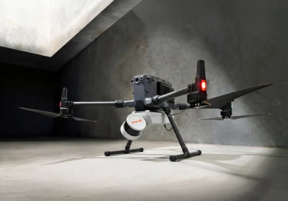
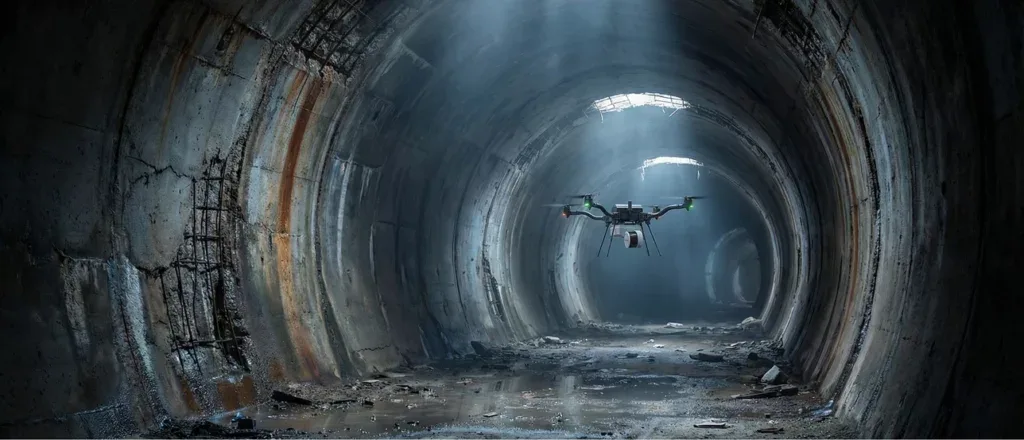
For field logistics, Artec lists Jet as manufacturer-published IP65, with an operating temperature of −10 to 45°C, a weight of 1.57 kg, and 512 GB of onboard storage, which it says is about 16 hours. Artec also lists seven deployment modes: handheld, backpack, drone, vehicle, cage, telescopic pole, and robot. That matters in terrain and infrastructure work because access method often decides whether a site can be scanned safely and efficiently at all. Artec’s current supported-drone list on the product page names DJI M300, DJI M350, and Freefly Astro Max. [1]
Accuracy isn’t one number: LiDAR accuracy vs mapping accuracy vs change detection
Jet’s accuracy claims need to stay separate. On the product page, the manufacturer-published LiDAR accuracy is ±10 mm. On the same page, the manufacturer-published mapping accuracy is ±15 mm in general environments and ±10 mm indoors or underground. Those are not interchangeable labels, and as accessed on July 28, 2026, the product page lists the figures but does not publish test conditions on-page for them. They should therefore be treated as manufacturer-published performance claims, not as acceptance values for any particular topographic survey deliverable. [1]
Artec also lists a manufacturer-published change detection capability of ±5 mm. That is useful, but it answers a different question from absolute positioning. A scan can be good for repeat comparison of a stockpile, embankment, tunnel wall, or erosion feature without automatically being correct enough in absolute coordinates to satisfy a control-heavy mapping deliverable. For terrain work, that means Jet may be attractive for monitoring and difference mapping, but checkpoints and georeferencing still matter whenever the output must be anchored to a project CRS and defended in QA. [1] [14]
Jet’s manufacturer-published drift specification is ±0.03%. A simple derived example shows why that should not be collapsed into a single “accuracy” number: 0.03% of 100 m is about 0.03 m, or 30 mm. That arithmetic is only a way to visualize potential scale; it does not mean every 100 m traverse will be off by 30 mm in every direction. It does mean that longer paths give drift more room to accumulate unless loop closures, route design, geometry, and external control help constrain the solution. That is why SLAM evaluation literature emphasizes loop closure and trajectory quality, and why Artec’s own accuracy caveat points back to geometry, duration, and control. [1] [22]
Scan-to-map workflow for terrain 3D scanning (field + office)
A professional terrain workflow starts before capture. With Jet, route design matters because SLAM performance depends on geometry, overlap, and opportunities for loop closure. In practical terms, that means avoiding long open traverses when possible, revisiting stable features when possible, and deciding in advance where GCPs, RTK, or checkpoints will be needed. Artec says Artec Twins can georeference scans using ground control points, RTK data, or both, so the control plan should follow the deliverable rather than the easiest walking path. [1]
In the office, the sequence usually goes from registration and trajectory cleanup to georeferencing, then classification, ground extraction, surface generation, and QA review. For terrain 3D scanning, classification is not optional, because raw point clouds are not yet a usable topographic surface. If the result will feed design, volume computation, or mapping, control and checkpoint review should happen before export. Artec’s Jet ecosystem materials list exports including LAS, LAZ, PLY, DXF, and E57, while USGS deliverables illustrate the broader expectation that validation documentation, survey reporting, and checkpoint evidence travel with the data rather than being treated as side notes. [2] [14]
| Deliverable goal | Relative-only SLAM OK? | Control required (GCP/RTK/checkpoints) | Minimum QA evidence to keep |
|---|---|---|---|
| Quick visualization / as-built | Usually yes | Optional if no coordinate target | Coverage notes, registration record, export record |
| Volume / stockpile | Sometimes | Recommended if quantities must be defensible | Control tie, assumptions, comparison method |
| Topo surface for design | Usually no | Yes | CRS, control list, checkpoint residuals, ground classification notes |
| Monitoring / change detection | Sometimes | Recommended | Repeat alignment method, dates, comparison settings |
| USGS/ASPRS-style acceptance required | No | Yes | Survey report, control documentation, checkpoints, validation records |
The logic is simple: the more the deliverable depends on being placed correctly in space, the less sufficient relative SLAM alone becomes. Jet can stay in a lighter workflow for visualization or internal monitoring, but once the output must survive external QA, the office workflow becomes part of the measurement system. [14] [15]
Terrain-specific failure modes
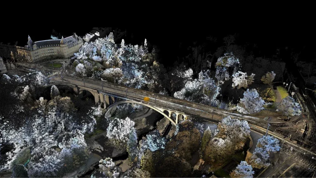
Open terrain can actually be harder for SLAM than a plant, tunnel, or corridor because it often gives the system fewer stable geometric anchors. Long smooth slopes, repeated textures, low vertical structure, and broad open areas can weaken trajectory constraints and make accumulated error harder to suppress. Artec’s note that actual accuracy depends on environment geometry, scan duration, loop closures, and whether GCPs or RTK are used is especially relevant in landscape work, where route design and control can dominate the outcome. [1] [22]
A useful independent reference point comes from a 2024 forest-canopy mobile laser scanning study, which is not Artec Jet testing. On an 800 m track, the study reported planar positioning error under 15 cm and vertical error of 10–30 cm for SLAM-plus-IMU systems under canopy. The lesson is not that Jet will behave the same way; it is that outdoor mobile mapping can degrade quickly when geometry, visibility, and classification get difficult. [20]
Terrain failure modes to plan for
- Sparse geometry: fewer stable features means weaker SLAM constraints and a greater need for loops or external control. [1] [22]
- Vegetation occlusion and ground visibility: if the ground is hidden, ground/non-ground classification becomes less certain and the resulting terrain model becomes harder to defend. [20]
- Water / reflective surfaces: returns may be sparse, unstable, or misleading, which raises risk in shoreline and wet-area modeling. [22]
- Dust / rain: environmental contamination can reduce data quality and complicate field QC. [1]
- Incidence angle effects: shallow viewing geometry on steep slopes can weaken returns and surface recovery. [22]
- Long corridors / one-way traverses: fewer closure opportunities increase drift risk over distance. [1] [22]
The practical takeaway is that terrain surveying is not only about whether a scanner can collect points. It is also about whether the site geometry supports stable reconstruction and whether the classified output can support the intended deliverable. [20] [22]
Jet vs Ray II (and why hybrid often wins)
Jet and Ray II solve different parts of the problem, so the comparison has to avoid false equivalence. Jet is the mobile option for fast coverage and flexible traversal, while Ray II is the stationary TLS option for denser, fixed-position capture and local reference quality. Artec explicitly says the two approaches complement each other and that users can merge Artec Jet and Ray II scans in Artec Twins. That is an important workflow clue: the most defensible answer is often not “Jet or Ray II,” but “where does each one add evidence?” [1]
For terrain and infrastructure work, a hybrid pattern often makes sense. Jet can cover the broad route, awkward access zones, or long corridors efficiently, while Ray II can lock down detail-critical areas, local reference zones, or QA anchors where stationary capture is worth the setup time. Ray II’s numbers also live in a different metric context: its manufacturer-published figures are 3D point accuracy at range, whereas Jet’s public figures are mapping-accuracy categories for a SLAM workflow. That difference alone is enough reason not to flatten them into a single “which is more accurate?” claim. [1] [4]
| Scanner/workflow | Best fit | Metric type & stated context | Main limitation |
|---|---|---|---|
| Artec Jet | Mobile terrain coverage, mixed indoor/outdoor routes, fast site traversal | mapping accuracy (SLAM, manufacturer-published) | Drift and control dependence over longer routes |
| Artec Ray II | Stationary reference zones, denser local capture, QA anchors | 3D point accuracy at range (stationary TLS, manufacturer-published) | Slower coverage and more setup |
| Other mobile SLAM systems | Coverage-first mobile mapping in the same general category | mobile SLAM context only | Results are system-specific and not normalized here |
| Structured-light handheld scanners | Close-range object capture and small-area detail | handheld close-range context only | Not suitable for broad terrain coverage |
Within that frame, Jet’s manufacturer-published range is 0.5–300 m, and its manufacturer-published mapping accuracy categories are ±15 mm in general environments and ±10 mm indoors or underground. Ray II’s manufacturer-published figures are 1.9 mm at 10 m, 2.9 mm at 20 m, and 5.3 mm at 40 m, with a manufacturer-published range of 0.5–130 m, capture rate up to 2,000,000 pts/sec, and field of view of 360° horizontal by 300° vertical. These are different measurement contexts, which is why hybrid use is often easier to defend than a one-scanner absolutist answer. [1] [4]
Standards and U.S. acceptance frameworks
ISO 17123-9 and ASTM E3125 are useful context, but they do not certify Jet. ISO 17123-9:2018 specifies field procedures for determining and evaluating the precision, or repeatability, of terrestrial laser scanners, and ISO says those tests are not proposed as acceptance or comprehensive performance evaluations. ASTM E3125 covers spherical coordinate 3D imaging systems in the medium range, defined as at least part of the 2 m to 150 m range, and focuses on derived-point to derived-point distance performance. NIST’s ASTM E3125 work helps explain what such standards-style testing can show for TLS-type systems, while its 2021 review also warns how hard it is to compare instruments purely from headline specs. [6] [7] [9] [10]
These standards are context, not certification of Artec Jet mobile SLAM performance, unless a direct SLAM validation method is cited. For U.S. public mapping, the more relevant frame is often the deliverables logic in the USGS Lidar Base Specification. USGS says the latest online version is LBS 2025 rev. A, released June 10, 2025. In its data handling requirements, USGS says all point deliverables shall be in LAS format, version 1.4-R15, using Point Data Record Formats 6 through 10. Its tables also show vertical-accuracy examples such as RMSE_v thresholds of no more than 0.100 m for QL1 and QL2 in nonvegetated areas. None of that proves Jet meets a quality level; it shows the kind of acceptance language a project may have to satisfy. [11] [12] [13]
The same logic applies to ASPRS accuracy reporting. ASPRS announced adoption of Edition 2, Version 2 in 2024, including new addenda such as mapping with lidar, and it stated that the minimum number of checkpoints for product accuracy assessment increased from 20 to 30. USGS’s summary of the change notes other reporting shifts as well, including removal of 95% confidence wording, RMSE term updates, and checkpoint-related changes. The FGDC-hosted briefing deck gives the same high-level picture. [15] [16] [17]
File formats and interoperability: LAS/LAZ vs E57
For U.S. topo and GIS-facing deliverables, LAS or LAZ is usually the practical language of exchange because it fits the way lidar data are validated, classified, tiled, and checked. USGS explicitly requires point deliverables in LAS 1.4-R15 using Point Data Record Formats 6–10 in its LBS handling requirements. The LAS 1.4-R15 specification also describes LAS as an open format for point cloud data exchange, with the cited revision date of July 9, 2019. If the downstream workflow is GIS, QA, or public lidar delivery, that is why LAS/LAZ usually matters more than the scanner’s internal processing path. [12] [18]
E57 fits a different role. ASTM E2807 describes the ASTM E57 3D file format as a container that can store 3D point data, associated attributes such as color and intensity, and 2D imagery. In Artec’s Jet ecosystem material, export formats include LAS, LAZ, PLY, DXF, and E57. So the decision is not “which format exists,” but “which format best fits the handoff.” LAS/LAZ is usually the easier path for U.S. topo deliverables and GIS pipelines; E57 is often more useful when the goal is scanner-to-scanner exchange or richer scene-context transfer between platforms and software. [2] [8]
Verdict: when Jet can be “best,” and when it isn’t
The Artec Jet 3D scanner can be the right answer when the winning condition is mobility, coverage speed, and operational flexibility. That includes sites where walking or driving a route is more practical than occupying multiple static stations, and jobs where relative consistency plus sensible georeferencing is more important than stationary reference capture everywhere. But Jet is not “best” in the abstract, because Artec’s own position is conditional: actual accuracy depends on geometry, scan duration, loop closures, and whether GCPs or RTK are used. [1]
It is not the strongest choice when the winning condition shifts to validated absolute accuracy, checkpoint defensibility, and QA traceability. In those cases, stationary TLS still has a role, and Artec’s own Ray II illustrates why with manufacturer-published 3D point accuracy at range of 1.9 mm at 10 m, 2.9 mm at 20 m, and 5.3 mm at 40 m. On price, Artec’s public prices page shows Jet with a “How to buy” entry and no visible USD figure on that listing, so no reliable official public USD price is provided there. The practical recommendation is therefore conditional: choose Jet for coverage-first terrain capture, and choose a more controlled or hybrid workflow when validation burden dominates. [3] [4]
FAQ
1. Is Artec Jet the best 3D scanner for landscape and terrain surveying?
Only under specific conditions. Jet is strongest when a job values mobility, route flexibility, and fast site coverage, and when the workflow can tolerate a SLAM-based mapping approach instead of fixed-station capture everywhere. It is not automatically the best choice for every topographic survey, because Artec says results depend on geometry, scan duration, loop closures, and whether GCPs or RTK are used. [1]
2. How accurate is the Artec Jet 3D scanner—what do ±10 mm, ±15 mm, and ±5 mm actually refer to?
They refer to different manufacturer-published claims, not one combined accuracy number. Artec lists LiDAR accuracy at ±10 mm, general mapping accuracy at ±15 mm, indoor or underground mapping accuracy at ±10 mm, and change detection capability at ±5 mm. As accessed on July 28, 2026, the product page lists those values without on-page test conditions, so they should not be treated as acceptance values by themselves. [1]
3. Do I need GCPs or RTK with Artec Jet for topographic work?
Usually yes if the deliverable must land reliably in a project CRS and survive QA review. Artec says actual accuracy depends in part on whether GCPs or RTK are used, and it says Artec Twins supports georeferencing with ground control points, RTK data, or both. If the job is only relative or visual, the control burden can be lighter; if it is survey-facing, it should be planned from the start. [1] [14]
4. Artec Jet vs Artec Ray II: which is better for industrial scanning and why might you combine them?
They are better at different things. Jet is the mobile, coverage-first option; Ray II is the stationary TLS option for local reference zones and denser fixed-position capture. Artec also says the technologies complement each other and that scans can be merged in Artec Twins, which is why a hybrid workflow often makes sense when one project needs both efficient site traversal and stronger local QA anchors. [1] [4]
5. What are the biggest SLAM LiDAR failure modes in open terrain (vs industrial plants/tunnels)?
The main risks are sparse geometry, weak loop-closure opportunities, vegetation that hides the ground, reflective water, dust or rain, shallow incidence angles on slopes, and long one-way traverses. Those conditions make both trajectory estimation and ground classification harder. Independent outdoor context supports the caution: a 2024 forest-canopy study on an 800 m track reported planar error under 15 cm and vertical error of 10–30 cm for mobile SLAM-plus-IMU systems, though that study was not Artec Jet testing. [20] [22]
6. Expert: How would you validate a SLAM point cloud for a deliverable that references ASPRS/USGS-style accuracy reporting?
You validate the deliverable, not just the scan. That means documenting the CRS, control strategy, checkpoints, classification steps, residuals, and the survey report that explains how the lidar and derivative products were validated. USGS deliverables make that explicit, and ASPRS Edition 2, Version 2 raised the minimum checkpoint count for product accuracy assessment from 20 to 30. [14] [16]
7. Expert: How do loop closures, route design, and non-rigid alignment affect drift and repeatability—and what evidence should you keep for QA?
Loop closures help suppress accumulated trajectory error by giving SLAM a chance to revisit known geometry. Route design determines whether those opportunities exist in the first place, especially in long open traverses. Artec also says Artec Twins can merge scans using SLAM-based non-rigid alignment, which is useful but should still be documented. For QA, keep route notes, control ties, alignment settings, residuals, checkpoint results, and export records. [1] [22]
Related on 3D Mag
- Artec Jet: the best 3D scanner for industrial plants
- Artec Spider II: the best 3D scanner for prosthetics and orthotics
Sources
- Artec Jet product page — https://www.artec3d.com/portable-3d-scanners/artec-jet
- Artec Jet launch announcement — https://www.artec3d.com/news/artec-jet-release
- Artec prices page — https://www.artec3d.com/prices
- Artec Ray II product page — https://www.artec3d.com/portable-3d-scanners/laser-ray
- ISO 17123-9:2018 standard page — https://www.iso.org/standard/68382.html
- ASTM E3125-17 standard listing — https://store.astm.org/e3125-17.html
- ASTM E2807-11R19 standard listing — https://store.astm.org/e2807-11r19.html
- NIST: A First realization of ASTM E3125-17 test procedures for laser scanner performance evaluation — https://www.nist.gov/publications/first-realization-astm-e3125-17-test-procedures-laser-scanner-performance-evaluation
- NIST: Performance Evaluation of Terrestrial Laser Scanners – A Review — https://www.nist.gov/publications/performance-evaluation-terrestrial-laser-scanners-review
- USGS Lidar Base Specification online landing page — https://www.usgs.gov/ngp-standards-and-specifications/lidar-base-specification-online
- USGS LBS Data Processing and Handling Requirements — https://www.usgs.gov/ngp-standards-and-specifications/lidar-base-specification-data-processing-and-handling-requirements
- USGS LBS tables — https://www.usgs.gov/ngp-standards-and-specifications/lidar-base-specification-tables
- USGS LBS deliverables — https://www.usgs.gov/ngp-standards-and-specifications/lidar-base-specification-deliverables
- USGS: Adopt updated accuracy standards — https://www.usgs.gov/ngp-standards-and-specifications/adopt-updated-accuracy-standards
- ASPRS approves Edition 2, Version 2 of the positional accuracy standards — https://old.asprs.org/archives/asprs-approves-edition-2-version-2-of-the-asprs-positional-accuracy-standards-for-digital-geospatial-data-2024.html
- FGDC-hosted ASPRS positional accuracy standard briefing PDF — https://www.fgdc.gov/ngac/meetings/april-2024/asprs-positional-accuracy-standard-ngac-apr-2024.pdf/at_download/file
- ASPRS LAS Specification 1.4 R15 PDF — https://www.asprs.org/wp-content/uploads/2021/04/LAS_latest.pdf
- Muhojoki et al. 2024 forest-canopy mobile laser scanning accuracy study — https://helda.helsinki.fi/server/api/core/bitstreams/d25b6ccb-92b8-4a30-9bbb-85a7545d0a8a/content
- Wiley: 3D LiDAR SLAM: A survey — https://onlinelibrary.wiley.com/doi/full/10.1111/phor.12497
- Sensors review: Mobile Mapping Systems — https://www.mdpi.com/1424-8220/22/11/4262
- FARO Orbis product page — https://www.faro.com/Products/Hardware/FARO-Orbis-Mobile-Laser-Scanner