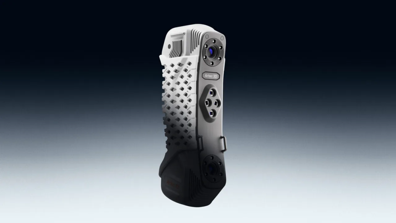

Editor’s note (September 2026): On August 5, 2026, Artec 3D released Artec Point II, which replaces Artec Point in the company’s metrology lineup. Point II keeps the certified 0.02 mm accuracy and the target-based workflow described below, but captures up to 5.8 million points per second, more than double the original, with 54 laser lines in ultra-fast mode, 17 parallel lines in hyperfine mode, and a single-laser mode for deep holes. Specifications and quotes below refer to the original Artec Point; read our Point II launch coverage for the current model.
Summary
Artec Point for scanning jewelry is a niche-fit tool rather than the default choice for tiny, gem-heavy work. Artec currently markets it as a handheld, target-based blue-laser scanner with manufacturer-stated 3D point accuracy up to 0.02 mm and 3D resolution up to 0.02 mm, but scanning with Point depends on keeping more than four marker points visible in the common field of view. [1] [4]
That requirement matters more for jewelry than the headline numbers do. On larger, metal-dominant pieces that can be fixtured cleanly, Point can be useful for inspection-oriented capture and reverse-engineering reference meshes. On very small parts, heavily polished surfaces, or gemstone-centered pieces, targets, access, and post-processing usually decide the outcome faster than the spec table does. Point also does not capture color, so any texture has to come from an external transfer workflow rather than onboard color capture. Within Artec’s lineup, Micro II is the mounted high-detail alternative with up to 5 microns accuracy, 2-micron repeatability, and 40 microns resolution, while Spider II is the target-free handheld alternative with up to 0.05 mm accuracy and 0.05 mm resolution. [1] [4] [6] [8] [9]
What “good for jewelry scanning” actually means
“Good for jewelry scanning” depends on the job, not the word jewelry itself. A scanner can be useful for inspection, reverse engineering, archive capture, or CAD remake support, but those are different output classes with different failure points. NIST’s range-performance work is a useful reminder that usable error depends on range, angle of incidence, reflectivity, azimuth angle, measurement method, and target type, not just the scanner model named on the box. [15]
Pick your goal:
- inspection dimensions
- reverse engineering reference mesh
- CAD-remake
- catalog/archival mesh
- gemstone capture
For jewelry, that distinction matters because a mesh that is good enough for visual reference may still be poor for scan-to-CAD, and a part that is easy to inspect may still be hard to digitize cleanly. The better question is not “Is Artec Point good for jewelry?” but “Which jewelry outcome do you need, and how much cleanup are you prepared to do?”
What Artec Point is (and the documentation contradiction you should know)
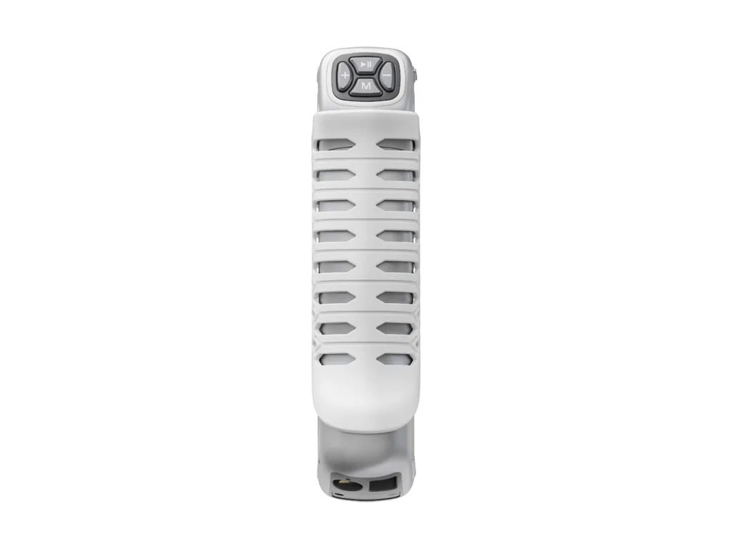
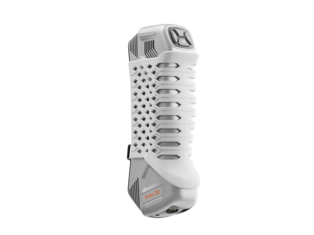
Artec currently markets Point as a handheld scanner, and its product page lists the scanner type as handheld. Artec’s press release dated Sep. 09, 2024 also describes Point as the company’s first target-based laser scanner. Taken together, that places Point on the metrology side of Artec’s portable lineup, not in the same workflow class as a mounted desktop jewelry scanner. [1] [2]
The public documentation is not fully consistent, however. Artec Studio 20 documentation calls Point an “automated desktop 3D scanner,” and the Quick Start Guide uses similar “compact, automated desktop 3D scanner” wording. Artec currently markets it as handheld; some official documentation describes it differently. [4] [7]
For jewelry buyers, that contradiction matters because workflow class matters almost as much as raw accuracy. A handheld, target-based metrology scanner behaves differently from a mounted small-object scanner when you are trying to digitize rings, settings, recesses, or tiny relief. The current marketing position is clear enough: Point is the handheld, target-based option, while parts of the documentation trail still contain older or conflicting desktop wording. [1] [2] [4] [7]
Why jewelry is hard to scan
Jewelry is difficult to scan because two different optical problems often appear in the same object. Reflective metals can return too much light in unstable ways, creating glare, noisy data, or tracking trouble instead of a clean surface read. Transparent gemstones create the opposite problem: optical systems need useful reflected light, but transparent materials transmit, refract, and absorb light in ways that undermine surface reconstruction. Artec’s own support material separates reflective and transparent materials for exactly these reasons, and independent research on transparent and glass objects likewise notes poor metrological performance for optical methods when diffuse reflection is missing. [12] [16]
Geometry makes the problem worse. Jewelry often combines undercuts, narrow recesses, fine relief, and blocked lines of sight in a very small package. Even when a surface can be seen at one angle, it may disappear behind a setting, gallery, shank, bezel, or prong from another. Partial capture is common, and CAD-ready work usually needs cleanup, hole management, and later reconstruction rather than simple one-click export. The issue is rarely that a shape is theoretically unscannable; it is whether the setup exposes enough of it, often enough, for a stable and useful dataset.
Common jewelry failure points:
- Mirror-like metal crowns or bezels.
- Clear stones or glass-like inserts.
- Undercuts under settings, shanks, and gallery structures.
- Tight recesses around prongs.
- Pavé or micro-detailed surfaces.
- Narrow bridge areas that block line of sight.
- Small parts that are difficult to fixture without obstruction.
- Surfaces that mix metal, stone, and polished transitions in one scan.
The practical bottleneck: targets and marker visibility on tiny parts
For Artec Point jewelry scanning, the biggest bottleneck is often marker visibility rather than nominal accuracy. Artec Studio’s Point documentation says that more than four marker points must be present in the scanner’s common field of view during scanning. On a ring, prong setting, pavé band, or small component, that can become awkward quickly because the object itself may hide targets, or the usable support area may simply be too small. [4]
Artec Studio provides 3 mm, 6 mm, and 12 mm targets for Point, plus target excision from 0 to 3 mm and a base cut-off threshold from 0 to 25 mm. In practice, the usual workaround is to put the targets on the fixture or base when the jewelry itself is too small or too sensitive to sticker directly. That solves one problem but creates another: targets and support geometry can obstruct access, and aggressive target excision or base removal can open holes or remove helpful context around the part. The same settings page also lists laser exposure from 0.1 to 10 ms and explicitly says to decrease it for highly reflective objects. [4]
So the feasibility question for Point is not just “Can it see the jewelry?” It is “Can it keep enough markers in view, on a support that does not hide the features you care about, while keeping the scan stable enough that cleanup remains manageable?” That is why Point can be workable on some jewelry jobs and frustrating on others.
Artec Point specs for jewelry: what the numbers can—and can’t—promise
Accuracy vs resolution vs volumetric accuracy
Artec’s own scanner page distinguishes accuracy from resolution, and that distinction matters here. Accuracy is about closeness to the true value of the measured quantity, while resolution is about how much detail the system can separate in the scanned object. Volumetric accuracy is different again: on Point, it is expressed as a formula over distance, which makes it most relevant when error accumulates across stitched extent rather than on one tiny local patch. [1] [3]
For Point, the manufacturer-stated figures are up to 0.02 mm 3D point accuracy and up to 0.02 mm 3D resolution. Artec also lists 3D accuracy over distance up to 0.015 mm + 0.035 mm/m, or up to 0.015 mm + 0.015 mm/m with the Artec Metrology Kit. The scanner’s capture rate is listed as up to 120 FPS and data acquisition speed up to 2.8 million measurements per second. Its three mode labels are ultra-fast with 17 crossed blue lasers, hyper-fine with 7 parallel blue laser lines, and deep hole with 1 single blue laser line. [1]
The working envelope matters too. Point is specified for a working distance greater than 300 mm, a scanning area up to 700 × 600 mm, a depth of field of 550 mm, and object size classes S to L. Those are useful metrology numbers, but they do not make Point a native substitute for a mounted micro-object workflow. On jewelry, volumetric accuracy matters more on a stitched bracelet span, watch case, or fixture-based setup than on one isolated tiny detail. [1]
Specs vs usable results:
- A 0.02 mm accuracy spec does not remove tracking and visibility problems if a polished part hides markers or destabilizes capture. [1] [4] [12]
- A 0.02 mm resolution spec does not guarantee clean gemstone edges or complete prong capture when the material is reflective, transparent, or both. [1] [12] [16]
- Volumetric accuracy matters most when error can accumulate across stitched views or larger extent, not as the only metric for a tiny isolated jewelry detail. [1]
- A 120 FPS capture rate and 2.8 million measurements per second improve throughput, but they do not change the optical behavior of the surface being scanned. [1] [12]
- NIST’s range-performance guidance shows that range, angle of incidence, reflectivity, azimuth angle, measurement method, and target type all affect range error. [15]
Is Artec Point good for jewelry? Verdict by use case
For dimensional inspection and tolerance checking, Point makes the most sense on metal-dominant pieces that are large enough, accessible enough, and stable enough to support a target-based setup. Think watch cases, larger rings, bracelets, buckles, or medallion-like parts where the goal is metrology-oriented geometry capture rather than gemstone realism. In that lane, the handheld format, stated 0.02 mm accuracy, and 0.02 mm resolution can be useful. [1] [4]
For reverse engineering, Point is most useful as a reference-mesh tool when portability matters. If the job benefits from scanning around a fixture, revisiting recesses deliberately, and using the result as geometry to rebuild from later, Point can be a reasonable fit. The capture is still constrained by targets and access, but it can supply workable reference data for metal-dominant forms that do not require a tiny desktop workflow. [1] [4]
For CAD remake, expectations should stay conservative. Point does not turn a raw jewelry scan into an editable parametric solid just because the product page lists CAD formats. In Artec Studio, STEP, IGES, and X_T exports apply to CAD primitives created in the software, not to raw scan data by default. That means mesh cleanup and later reverse engineering still sit between capture and editable CAD. [1] [5]
For gemstones and highly reflective finishes, the answer drops from “sometimes useful” to “proceed carefully.” Reflective metal can still create noisy or unstable data, and transparent stones remain especially problematic for optical methods because the needed diffuse reflection is absent. No reliable figure was found for consistent gemstone success rates with Artec Point on jewelry-grade transparent stones, so it is safer to treat those cases as workflow risks rather than promises. [12] [16]
Use Artec Point when…
- You need portable metrology-style capture of a larger jewelry-related part or metal-dominant piece. [1]
- You can fixture the object so that more than four markers stay visible in the common field of view. [4]
- You want an inspection mesh or reverse-engineering reference mesh, not a finished parametric CAD model from the raw scan. [1] [5]
- You can rescan recesses deliberately instead of expecting one sweep to capture everything cleanly. [1] [4]
- The critical surfaces are mostly opaque metal rather than transparent gemstone geometry. [12] [16]
Choose another scanner when…
- The part is so small that a mounted small-object workflow is the more natural fit. [8]
- Marker placement would block access or make it hard to keep more than four markers visible. [4]
- The finish is highly reflective and the setup cannot control angle, access, or exposure well enough. [4] [12]
- Transparent gemstones are central to the job. [12] [16]
- You need the highest-detail mounted workflow in Artec’s own lineup rather than portable target-based capture. [8]
Artec Point vs Micro II vs Spider II
| Scanner | Best-fit jewelry role (task-based) | Key sourced specs (separate metrics) | Main caveat |
|---|---|---|---|
| Artec Point | Portable metrology capture for larger pieces and fixture-based work. [1] | Target-based and handheld, with up to 0.02 mm accuracy, up to 0.02 mm resolution, and working distance greater than 300 mm. [1] | It depends on marker visibility, so it is less convenient when targets are hard to place or keep in view. [4] |
| Micro II | Mounted high-detail capture for tiny jewelry parts and small components. [8] | Desktop workflow, with up to 5 microns accuracy, 2-micron repeatability, 40 microns resolution, object size up to 20 × 20 × 15 cm, and an ISO12836 accuracy certificate. [8] | Its ISO 12836 context is for mounted devices and does not transfer directly to handheld scanner comparisons. [13] |
| Spider II | Handheld detail scanning when markers are impractical. [9] | Target-free, with up to 0.05 mm accuracy, up to 0.05 mm resolution, 30 fps, working distance 0.19–0.3 m, and color + geometry tracking. [9] | It is a different workflow class from Point, with lower stated accuracy than Point and less of a target-based metrology emphasis. [1] [9] |
For jewelry buyers, the biggest tradeoff is workflow fit, not just the smallest printed number. Point is the portable, target-based metrology choice when markers can be placed and kept visible. Micro II is the small-object specialist when the part can be mounted and scanned as a desktop job. Spider II is the simpler handheld path when targets are impractical and color capture is useful. [1] [8] [9]
Listed U.S. price at access date: Point US $29,900, Micro II US $24,240, and Spider II US $29,700. That is useful as buying context, but it is not a substitute for matching the scanner to the workflow. [3]
How to scan jewelry with Artec Point
Start with setup decisions, not scan speed. Before you power up, decide whether the piece can be mounted securely, whether temporary coating is permitted for the use case, and whether the critical geometry will still be visible once the object is fixtured. On jewelry-scale jobs, a stable setup usually matters more than a fast first pass. [1] [4]
Next, plan targets around the fixture rather than assuming the jewelry itself should carry them. Point scanning requires more than four markers in the common field of view, so support geometry often has to do part of the tracking work. The key is to place markers where they remain visible without covering edges, settings, relief, or other surfaces you need to keep. [4]
Then match the capture approach to the geometry. Point’s modes are ultra-fast, hyper-fine, and deep-hole, and Artec lists capture up to 120 FPS and up to 2.8 million measurements per second. Those figures help with throughput, but on jewelry they do not remove the need to lower exposure on highly reflective zones, revisit recesses, and rescan difficult areas deliberately. Artec Studio’s Point settings list laser exposure from 0.1 to 10 ms and explicitly advise decreasing it for highly reflective objects. [1] [4]
Practical Artec Point jewelry workflow:
- Confirm that the piece can be held steady without hiding the geometry you need.
- Confirm that you can keep more than four markers visible in the common field of view. [4]
- Mount the item or fixture so critical surfaces remain exposed.
- Put markers on the base, fixture, or accessible support areas when the jewelry itself is too small or too sensitive to sticker directly. [4]
- Select target size and removal settings deliberately; Artec Studio provides 3 mm, 6 mm, and 12 mm targets, target excision from 0 to 3 mm, and base cut-off from 0 to 25 mm. [4]
- Lower laser exposure for highly reflective areas; the Point exposure range is 0.1 to 10 ms. [4]
- Scan the main accessible surfaces first to establish stable geometry.
- Use Point’s mode options as needed, and rescan recessed or deep-hole areas deliberately rather than trying to force everything into one sweep. [1]
- Review coverage and tracking before breaking the setup.
- Move into post-processing only after the object is fully captured and the scan is stable.
From point clouds to meshes to CAD: what you can actually export
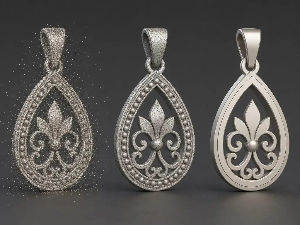
Point’s practical output is mesh-first. Artec’s product page lists 3D mesh outputs such as OBJ, PLY, WRL, STL, AOP, ASC, Disney PTX, E57, and XYZRGB, and it also lists CAD formats such as STEP, IGES, and X_T. That can be misleading if read too quickly, because the presence of CAD formats on the product page does not mean a raw jewelry scan becomes an editable parametric CAD model by default. [1]
Artec Studio’s project documentation is the key qualifier: STEP, IGES, and X_T exports apply to CAD primitives created in Artec Studio. The same documentation also notes that polygonal models created in Artec Studio are insufficient for most design needs and points users toward reverse-engineering workflows when manufacturing-ready CAD is the goal. In short, raw scan data is geometry data, not a ready-made parametric solid. [5]
Typical scan-to-CAD pipeline for jewelry:
- Capture the object as scan data and generate point clouds or meshes. [1]
- Check tracking and coverage for drift, missed recesses, or marker-related gaps. [4]
- Clean the mesh by removing stray geometry and dealing with small holes.
- Rebuild only the features that need CAD logic, such as planes, cylinders, profiles, or controlled surfaces.
- Export STEP, IGES, or X_T only after those CAD objects have been created in Artec Studio. [5]
- Treat the raw scan as reference geometry, not as an editable parametric solid.
- Save project data separately from final exchange files. [5]
For exchange, E57 is a point-data format, not a CAD-solid format. The ASTM E57 summary says an E57 file can store 3D point data, attributes such as color and intensity, and 2D imagery. Texture is a separate issue again: Point does not capture color, and Artec’s support article describes texture transfer to a Point fusion from an external photogrammetry model. [18] [6]
Standards and certifications: what they mean, what they don’t
Artec states that Point’s certification context is “ISO 17025 accredited based on VDI/VDE 2634 & JJF 1951,” and the Sep. 09, 2024 press release says the scanner was verified in an ISO-certified lab against those standards. That wording is relevant metrology context, but it is still manufacturer wording about a lab-based verification context. ISO/IEC 17025 itself is the international standard for testing and calibration laboratories, meaning it is about laboratory competence, impartiality, and consistent operation. It is not a guarantee that every real jewelry setup will deliver the same result on reflective, transparent, occluded, or poorly fixtured parts. Artec’s public materials name VDI/VDE 2634 and JJF 1951, but no reliable VDI/VDE part number was found in those public materials. [1] [2] [14]
Micro II’s standards context is different. Artec lists an ISO12836 accuracy certificate for Micro II, but ISO 12836:2015 explicitly says its methods require a mounted digitizing device and do not apply to hand-held scanning devices. That makes the certificate useful for understanding Micro II’s mounted-device metrology context, but it should not be transferred directly to handheld Point use. [8] [13]
Limitations, coatings, and risk cases
Reflective metals and transparent gemstones are still the two major jewelry risk cases, but they are not the same problem. Reflective metal can create unstable returns, glare, or noisy geometry, while transparent stones often defeat the basic optical assumption that the surface will diffusely reflect usable light back to the system. That is why some metal-dominant pieces remain workable with careful setup, while transparent stones stay a much harder sell. [12] [16]
Coatings and matting sprays can help, but they should be treated as process variables, not dimensionally neutral assumptions. The available research cited here shows that the number of spray passes and the skill of the operator can significantly affect structured-light scanning performance. So if coating is allowed at all, it should be validated on the actual part and workflow rather than treated as a universal fix. [17]
When to avoid coating:
- Final dimensional capture where any added layer is unacceptable.
- Stones, settings, or finishes that must remain untouched.
- Heirloom, appraisal, or condition-sensitive work.
- Cases where coating could obscure sharp edges, engravings, or prongs.
- Repeated comparison workflows where coating consistency cannot be controlled.
Bottom line on Artec Point for scanning jewelry
Artec Point for scanning jewelry makes the most sense when the job looks like portable metrology on larger, marker-friendly pieces rather than tiny mounted detail capture. Artec positions Point as a handheld, target-based scanner with stated accuracy and resolution up to 0.02 mm, but its practical feasibility still depends on keeping more than four markers visible during scanning. For tiny mountable parts, Micro II is the more natural fit inside Artec’s lineup because it is the mounted high-detail option with up to 5 microns accuracy and 2-micron repeatability. When targets are not feasible and a handheld workflow matters more, Spider II is the cleaner alternative. [1] [4] [8] [9]
FAQ
Is Artec Point good for jewelry?
Yes, for some jewelry tasks. It is strongest when you need portable, target-based metrology capture of metal-dominant pieces that can be fixtured cleanly and scanned with stable marker visibility. It is less convincing as a default scanner for very small, gemstone-heavy, or highly obstructed jewelry jobs. [1] [4] [12] [16]
Does Artec Point need targets for jewelry scanning?
Yes. Artec Studio’s Point documentation says that more than four marker points must be present in the common field of view during scanning, and the available target sizes are 3 mm, 6 mm, and 12 mm. That is workable on fixture-based jobs, but it becomes restrictive on tiny parts. [4]
Can Artec Point scan reflective gold or silver jewelry?
Sometimes, but reflective metal remains a real limitation for optical scanning. Artec’s support documentation says reflective surfaces reflect too much, which can destabilize capture or degrade surface quality. Lowering exposure and changing angle or setup can help, but they do not guarantee a clean result. [4] [12]
Can Artec Point scan diamonds or transparent gemstones?
Transparent gemstones are especially problematic for optical 3D methods because the needed diffuse reflection is not available in the normal way. Artec’s support material and independent ISPRS research both support a conservative view here, and no reliable figure was found for consistent Point success rates on transparent jewelry stones. [12] [16]
Does ISO/IEC 17025 mean I’ll get 0.02 mm on real jewelry?
No. ISO/IEC 17025 is about laboratory competence context, not guaranteed field performance on every part. Artec’s 0.02 mm figure is a manufacturer-stated spec, and the actual result still depends on setup, targets, access, reflectivity, geometry, and post-processing. [1] [2] [14]
Why can’t I just export a scan as STEP and edit it like CAD?
Because Artec Studio’s CAD exports apply to CAD primitives created in the software, not to raw scan data by default. A raw scan is point-cloud or mesh geometry. Editable parametric CAD usually requires cleanup and reverse engineering before STEP, IGES, or X_T becomes meaningful. [5]
Point vs Micro II vs Spider II: which is best for my workflow?
Choose Point if you need portable metrology-style capture and can support a marker-based setup. Choose Micro II if the part is tiny and can be scanned as a mounted desktop job. Choose Spider II if markers are impractical and you want a target-free handheld workflow with color capture. [1] [8] [9]
Related on 3D Mag
- Artec Micro II: Is It the Best Jewelry 3D Scanner?
- Artec Micro II vs Artec Point for Jewelry
- Exploring the Different Types of 3D Scanners
Sources
- Artec Point product page — https://www.artec3d.com/portable-3d-scanners/laser-point
- Artec Point press release — https://www.artec3d.com/news/artec-point-press-release
- Artec portable scanners page — https://www.artec3d.com/portable-3d-scanners
- Artec Studio 20 documentation: Scanning — https://docs.artec3d.com/as/20/en/scan.html
- Artec Studio 20 documentation: Projects and CAD object export — https://docs.artec3d.com/as/20/en/projects.html
- Artec Support: How to Texture an Artec Point Fusion — https://support.artec3d.com/hc/en-us/articles/32222874832786-How-To-Texture-an-Artec-Point-Fusion
- Artec Point Quick Start Guide v1.5 — https://docs.artec3d.com/point/Quick%20Start%20Guide/1.5%20Artec%20Point%20Quick%20Start%20Guide.pdf
- Artec Micro II product page — https://www.artec3d.com/portable-3d-scanners/artec-micro
- Artec Spider II product page — https://www.artec3d.com/portable-3d-scanners/artec-spider
- Artec jewelry solutions page — https://www.artec3d.com/3d-scanning-solutions/jewelry
- Artec case study: Cooksongold jewelry and Artec Micro — https://www.artec3d.com/cases/cooksongold-jewelry
- Artec Support: Black, reflective, transparent, etc. surfaces — https://support.artec3d.com/hc/en-us/articles/360012679439-Black-reflective-transparent-etc-surfaces
- ISO 12836:2015 summary page — https://www.iso.org/standard/68414.html
- ISO/IEC 17025:2017 summary page — https://www.iso.org/standard/66912.html
- NIST Technical Note 1695 publication page — https://www.nist.gov/publications/characterization-range-performance-3d-imaging-system-nist-tn-1695
- ISPRS Archives paper on transparent and glass surface digitization — https://isprs-archives.copernicus.org/articles/XLIII-B2-2022/695/2022/isprs-archives-XLIII-B2-2022-695-2022.html
- Influence of coating spray on surface measurement using 3D optical scanners — https://experts.illinois.edu/en/publications/influence-of-coating-spray-on-surface-measurement-using-3d-optica/
- ASTM E2807-11R19 summary page for E57 — https://store.astm.org/e2807-11r19.html