
Summary
Over extrusion is the shop-floor term many FDM/FFF users use when a printer deposits more plastic than the slicing setup expects. In practitioner guidance, the core idea is simple: excess material shows up because the printer is delivering more plastic than the software intended. [4]
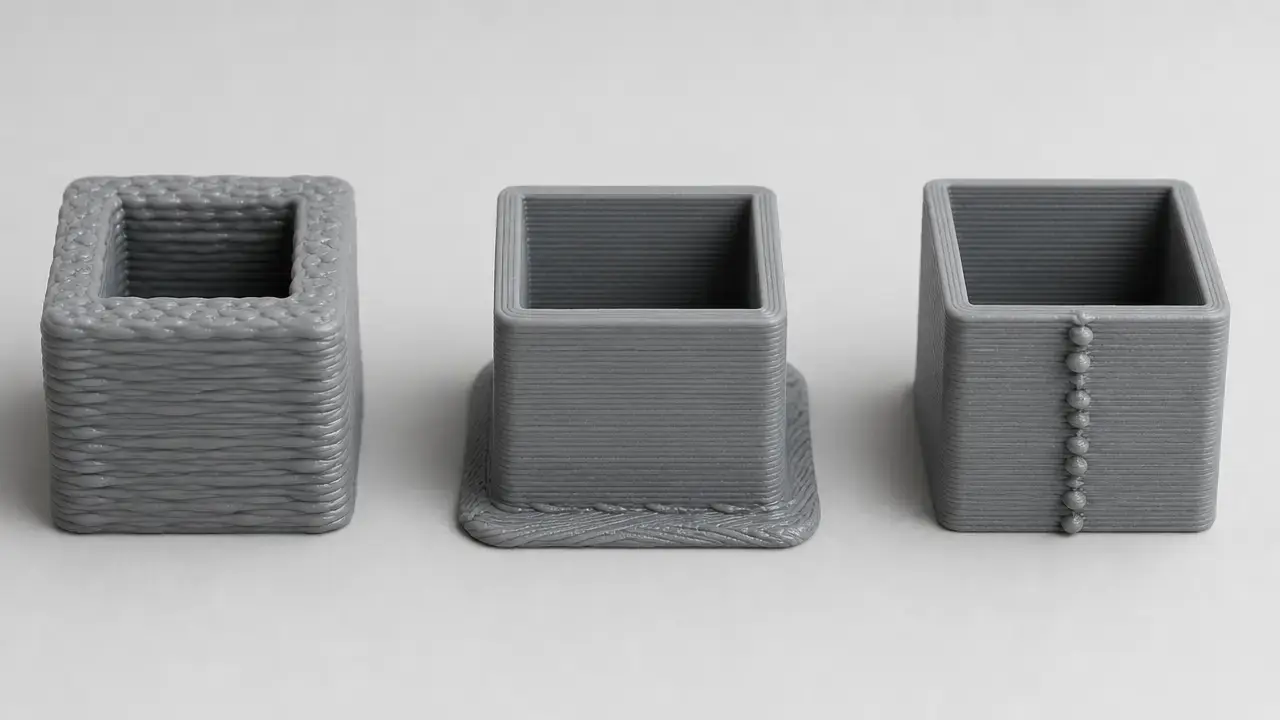
Several different problems can look like one 3d printer over extrusion complaint. Broadly, they fall into three buckets: A) Global excess deposition, where the commanded amount is too high; B) First-layer overcompression, where the nozzle is too close and the plastic is flattened; and C) Seam/start-stop pressure artifacts, where restarts and pressure changes leave local blobs or zits. Firmware and slicer multipliers can compound, and a too-low first layer can mimic excess flow, so the safest path is to diagnose first and calibrate in order. [6] [7]
Quick diagnosis first — three mechanisms that look like over extrusion
In standards language, ISO/ASTM 52900:2021 is a vocabulary reference for additive manufacturing, published in 2021-11 as a 28-page second edition and confirmed in 2025. It is useful here as a terminology anchor, not as a defect-class rulebook for this symptom. In day-to-day printer troubleshooting, “over extrusion” is better treated as a practitioner label for visible excess plastic relative to software expectation. For diagnosis, keep the problem in three buckets: A) Global excess deposition, B) First-layer overcompression, and C) Seam/start-stop pressure artifacts. [1] [4]
Do not start by changing multiple flow-related controls at once. If firmware flow override and slicer extrusion multiplier are both active, they can stack into a double correction. That can make the printer look improved for the wrong reason, or worse for no obvious reason. First decide which of the three mechanisms you are looking at, then change the smallest relevant control. [6]
| Symptom pattern | Likely mechanism | First check | Do not change yet |
|---|---|---|---|
| Rough top layers and excess material across the whole part. | A) Global excess deposition. | Slicer flow/extrusion multiplier and any firmware M221 override. [4] [6] [13] | Z-offset. |
| Ridges, dragging, or flattening only on the first layer. | B) First-layer overcompression. | Z-offset and first-layer calibration. [7] | Global flow. |
| Blobs or zits at the seam or only at starts/stops. | C) Seam/start-stop pressure artifacts. | Seam placement, retraction/restart behavior, and pressure compensation settings. [5] [14] [16] | E-steps or rotation_distance. |
| Oversized dimensions without obvious excess ridges. | Could be geometry or compensation, not necessarily A. | Check where the error appears, especially whether it is first-layer-related or tied to slicer geometry assumptions. [7] [9] [17] | The assumption that size error alone proves over extrusion. |
Use that table as a triage tool, not a final verdict. The same print can show more than one mechanism at once, but the first place the defect appears usually tells you where to start.
Over extrusion signs and lookalikes — what it looks like on real prints
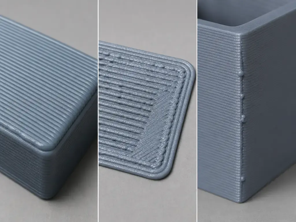
The most useful 3d printing signs of over extrusion are the ones that appear across the whole part, not just at one seam or on one bed-facing layer. In global excess deposition, top surfaces can look overfilled, wall lines can crowd each other, nozzle drag can scar the surface, and features can look slightly swollen rather than crisp. Simplify3D frames the problem as excess plastic that can ruin outer dimensions, while Prusa’s extrusion multiplier guide ties incorrect flow to scarring and buildup on finished surfaces. [4] [6]
Localized seam marks are different. Simplify3D’s blobs-and-zits guidance describes them as start/stop artifacts, so a part can have generally correct walls and still show visible blemishes exactly where the toolpath restarts. [5]
First-layer symptoms are the most common lookalike. Prusa’s first-layer guidance shows that when the nozzle is too low, the line can be squashed flat, ridges can form between lines, edges can curl, and in extreme cases the hotend can clog. That is a geometry and nozzle-height problem first, not automatic proof that the whole print needs less flow. [7]
Common signs of over extrusion
- Rough top layers or an overfilled top skin. [4] [6]
- Raised ridges between adjacent lines. [7]
- Bulging walls or “swollen” features. [4]
- Scarring where the nozzle drags through excess material. [6]
- Blobs or zits at seams or starts/stops. [5]
- First-layer ridges from too much squish. [7]
Causes, grouped by mechanism so the fix matches the physics
It helps to treat over extrusion as an outcome label rather than a single root cause. The visible result is “too much plastic here,” but the reason may be a true flow mismatch, a bad first-layer geometry setup, or restart pressure behavior that only affects one point in the toolpath. Prusa’s warning about compounded multipliers matters here: if firmware flow and slicer flow are both active, the apparent defect may be the product of both settings rather than a single bad value. [6]
Change one variable at a time, keep the same model and material when comparing results, and write down the old value before you change it. That prevents a seam artifact from being “fixed” by a global change, or a first-layer issue from being hidden by lowering flow everywhere.
| Cause | Symptom | First check | Fix category |
|---|---|---|---|
| Mechanism A — Global excess deposition | |||
| Slicer extrusion multiplier or flow ratio too high. [6] | Rough tops, buildup, swollen walls. | Filament/profile flow setting. | Profile-level flow tuning. |
Firmware flow override too high, such as M221 S<percent>. [13] |
Whole part looks fat or overfilled. | LCD or console override state. | Reset or normalize firmware override. |
| Filament diameter mismatch in a workflow that uses diameter input. [10] [11] | Global volume mismatch. | Material diameter setting in the slicer profile. | Correct profile/material input. |
| Nozzle or line-width assumptions are wrong. [9] [17] | Wall overlap, rough skin, inconsistent wall thickness. | Nozzle size, line width, and related slicer geometry. | Correct geometry assumptions. |
| Mechanism B — First-layer overcompression | |||
| Z-offset too low. [7] | Layer-one ridges, dragging, widened base. | First-layer test patch or live Z check. | Raise nozzle and redo first-layer calibration. |
| Mechanism C — Seam/start-stop pressure artifacts | |||
| Restart or priming is too aggressive. Simplify3D’s example shows 1.0 mm retraction plus -0.2 mm extra restart yielding 0.8 mm restart. [5] | Blob at seam start. | Extra restart, wipe, or coasting behavior. | Seam-focused slicer tuning. |
| Corner and restart pressure dynamics. Pressure Advance in Klipper and Linear Advance in Marlin belong here, not in the global-flow bucket. [14] [16] | Corner blobs, seam marks, local overfill. | Pressure-compensation procedure for your firmware. | Firmware pressure compensation, used carefully. |
How to fix over extrusion on a 3D printer — diagnosis-first workflow
When readers ask how to fix over extrusion on a 3D printer, the safest answer is an ordered one. Start by deciding whether the defect is global, first-layer-only, or seam-localized. If it is only on the bed-facing layer, check Z-offset before touching flow. If it is confined to the seam, inspect restart behavior and pressure timing before recalibrating anything global. If it affects the whole part, then look at slicer flow, firmware override, and profile assumptions. [7] [6]
Next, return the machine to a known baseline. Clear any temporary firmware flow override, confirm the nozzle size in the slicer matches the actual nozzle, and confirm whether your workflow exposes a filament diameter field. Then separate motion calibration from deposited-plastic tuning. In Marlin, M221 is a firmware flow override, while M92 sets steps-per-unit and can be saved with M500 when EEPROM is enabled. In Klipper, rotation_distance calibration uses a slow extrusion test: mark filament around 70 mm from the intake, extrude 50 mm with G91 and G1 E50 F60, let the move take about 50 seconds, and repeat if the error exceeds about 2 mm. That slow test is specifically meant to reduce pressure-related skew in the measurement. Only after motion is known to be correct should you tune slicer flow for a given material and profile. [13] [12] [15]
Keep the changes small. Prusa’s visual method suggests 1–2% flow adjustments, not big jumps, because large edits can hide the real mechanism and send you chasing a symptom instead of fixing a cause. [6]
- Save the current slicer profile and note any firmware flow override that is active. [13]
- Confirm the installed nozzle diameter matches the slicer nozzle setting. [9]
- Confirm any filament diameter setting your workflow exposes or uses. [10] [11]
- Re-run a first-layer or Z-offset check before changing flow if the issue is first-layer-only. [7]
- Verify extruder motion calibration only if commanded filament movement is measurably wrong. [12] [15]
- Print a controlled flow or extrusion multiplier test. [6]
- Adjust in small increments, such as Prusa’s 1–2% visual-method steps. [6]
- Re-test with a real part and compare seam behavior, top surfaces, and the first layer before changing anything else. [5] [7]
Motion calibration boundary — E-steps in Marlin and rotation_distance in Klipper vs flow
Motion calibration sets how much filament movement the firmware commands, not how good a printed wall looks. In Marlin, M92 sets steps-per-unit, including the E axis, and the documentation shows an example like M92 E688.4. In Klipper, rotation_distance is the corresponding extruder-motion parameter, defined as the distance the filament travels for one full rotation of the stepper motor. [12] [15]
That boundary matters because print appearance alone is a poor way to tune motion constants. A squashed first layer, a seam blob, and a true global flow mismatch can all make a part look overfed, but only one of those is actually an extruder-motion calibration problem. Klipper’s own procedure uses slow extrusion specifically because higher pressure can skew the result, and it recommends repeating the test if the measured error differs from the requested extrusion by more than about 2 mm. Keep the three mechanisms separate: motion calibration first when needed, then flow tuning, then seam-specific timing tools. [15]
Flow tuning — extrusion multiplier / flow ratio in the slicer vs firmware flow override
Flow in a slicer is a multiplier applied to commanded extrusion, not a motor-distance calibration. That distinction matters because the slicer multiplier and a firmware-side override can stack. Prusa states the relationship directly: total flow rate equals the firmware flow multiplier (M221) times the slicer extrusion multiplier. In Marlin, M221 S<percent> is the firmware-side control. [6] [13]
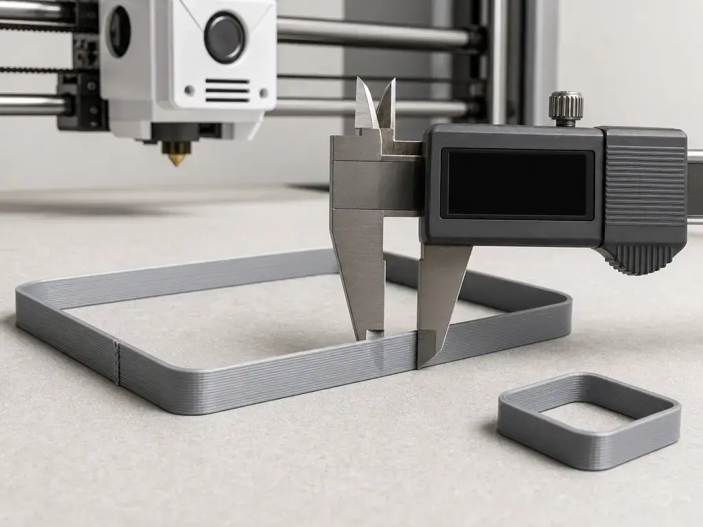
Prusa’s calibration page is useful as an example, not a universal law. For PLA, it lists a default extrusion multiplier of 1, meaning 100%, and says adjusted values are usually between 0.9 and 1.1. Its precise method assumes a default-profile context of a 0.4 mm nozzle, 0.45 mm extrusion width, 0.1–0.2 mm layer height, and extrusion multiplier 1. For the single-wall method, it instructs users to take three or more measurements in the middle of each wall and use the example formula extrusion multiplier = 0.45 / average measured wall thickness. Treat that as a practical heuristic, not metrology: sample mid-wall, take multiple readings, avoid seams, and avoid the first layers. In the visual method, Prusa recommends 1–2% re-adjustments if the top surface still needs correction. [6]
Flow % vs throughput limits
- Flow % / extrusion multiplier / flow ratio = slicer-side multiplier to commanded extrusion. [6]
- M221 = firmware-side flow override multiplier in Marlin. [13]
- E-steps / rotation_distance = motion calibration for filament feed distance. [12] [15]
- Max volumetric speed = hotend melt-capacity limiter in mm³/s, not a flow percentage. [8]
Seams, blobs, and zits — when it is pressure and timing, not global over extrusion
If you are asking why do I get blobs on my 3d prints, the short answer is that the nozzle is often leaving a localized start/stop mark at the seam instead of overfeeding the whole part. Simplify3D describes blobs and zits as artifacts that appear where extrusion stops and starts. Its restart example is a useful illustration: with 1.0 mm retraction and -0.2 mm extra restart, the nozzle only primes 0.8 mm on restart. The same page gives 5 mm wipe distance as a starting point and says 0.2–0.5 mm of coasting can have a noticeable effect. Those are slicer-specific examples, but they show the principle clearly. [5]
Pressure-compensation tools belong in this seam-and-corners bucket. Klipper’s Pressure Advance page gives tuning-tower factor examples of .005 for a direct-drive extruder and .020 for a long Bowden setup, and says typical values fall between 0.050 and 1.000, with the higher end usually associated with Bowden systems. It also says Pressure Advance depends on the extruder, nozzle, and filament and should be calibrated per spool. Most importantly, it states that Pressure Advance does not change the total amount of filament extruded during a print. In Marlin, M900 sets or reports Linear Advance K, and K0 disables it. Use these as timing tools for blobs on print, not as substitutes for flow-rate calibration. [16] [14]
Geometry coupling — nozzle diameter, line width, layer height, and filament diameter
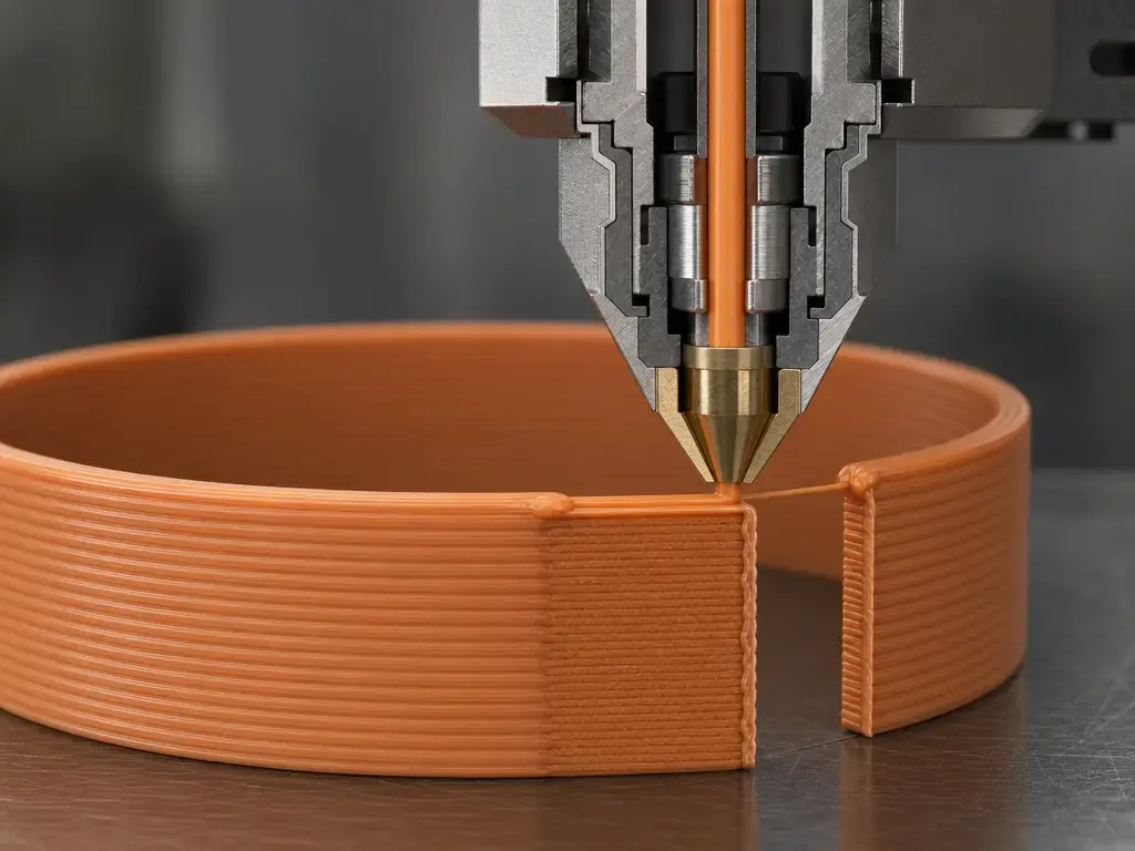
Slicers do not simply tell the printer to lay down a perfect round strand. They compute bead geometry from nozzle diameter, line width, and layer height, then use that geometry to decide spacing and volume. Slic3r’s flow math is a helpful reference: it defaults external perimeter width to nozzle diameter × 1.05, treats that as the thinnest safe external width, and caps calculated extrusion width at nozzle diameter × 1.7 except for internal sparse infill. It also shows that path spacing depends on both extrusion width and layer height through the formula spacing = extrusion_width - layer_height * (1 - PI/4). The practical takeaway is simple: wrong nozzle or line-width assumptions can create overlap, rough surfaces, or size changes that look like over extrusion even when the flow multiplier itself is not the main problem. [9]
Filament diameter still matters, but conditionally. Slic3r exposes a user-updatable Diameter field, and Cura’s base extruder definition still includes a material_diameter setting with a default of 2.85 mm plus the instruction to match it to the actual filament used. That does not mean every modern profile depends on diameter in the same way, and it does not mean diameter explains every defect. It means you should verify whether your chosen workflow is using that value and whether it matches the material actually loaded. [10] [11]
Throughput limits that can masquerade as flow problems, but are not the same thing
A print can look inconsistently extruded even when the flow setting is reasonable, because the hotend may be reaching its melt-capacity limit. Prusa defines maximum volumetric speed as the maximum amount of plastic the hotend can reliably melt, expressed in mm³/s, and describes it as a speed limiter that only reduces requested speeds when the hotend would otherwise be asked to melt more than it can handle. [8]
That is a different mechanism from a flow multiplier. Flow percentage changes the amount of material requested by the toolpath. A throughput limit caps the melt rate or speed the hotend can sustain. If a part degrades mainly when you print faster or use more aggressive line width and layer height combinations, the problem may be melt capacity rather than a bad flow calibration. [8]
What to measure after a fix
After any correction, the goal is repeatable part quality, not a magic number. One successful print can be misleading if the original defect was really a first-layer issue or a seam artifact rather than a global flow problem. [5] [7]
Use the same filament, nozzle, slicer profile, and model family when you verify the result. A first-layer patch isolates Z-offset and first-layer squish. A vase-mode single-wall cube or cylinder isolates profile-level flow behavior. A seam-comparison tower or similar part isolates restart and seam behavior. A simple calibration block can still be useful, but use it carefully: oversized dimensions alone do not prove over extrusion, because first-layer widening, geometry assumptions, and slicer path planning can also change external size. For the single-wall test, follow Prusa’s sampling rule: take three or more measurements, do them in the middle of each wall, and stay away from the seam and the first layers. That makes the result a much better comparison tool, even if it is still a heuristic rather than a universal pass/fail test. [6] [7] [9] [17]
| Metric | How to measure | What it validates |
|---|---|---|
| Wall thickness | Measure mid-wall on a single-wall print, with multiple readings away from the seam. [6] | Profile-level flow consistency. |
| Top-surface feel and appearance | Inspect for smoothness, scarring, and obvious overfill on the same test part. [6] | Whether global excess deposition remains. |
| Seam visibility | Compare restart marks on the same seam-oriented model. [5] | Start/stop pressure behavior. |
| First-layer ridges | Inspect the patch for flattening, drag marks, and curl. [7] | Z-offset and first-layer geometry. |
| Fit or assembly behavior | Compare the same mating feature after the change, without treating size alone as proof of over extrusion. [7] [17] | Overall practical repeatability. |
Common mistakes and limitations
A common mistake is lowering flow as the first response to any messy-looking print. That can hide the wrong problem and create under-extrusion elsewhere. If the real issue is nozzle height, seam behavior, or a bad geometry assumption in the profile, a lower flow number may make one symptom look better while moving the print farther away from a correct baseline. Simplify3D’s definition is useful here because it centers the problem on excess plastic relative to software expectation. The real question is which setting created that mismatch, not how quickly you can lower flow. [4]
Hardware condition can also mislead you. A worn nozzle can change the effective orifice geometry and nozzle height, which in turn affects dimensional accuracy. A 2023 academic repository record on nozzle wear reports that abrasive filaments changed both nozzle orifice diameter and nozzle height, with dimensional effects on printed PLA samples. Do not tune flow to compensate for a nozzle that is physically no longer the size your profile assumes. [18]
Temperature is another place people oversimplify the problem. In practice, it affects melt viscosity, pressure in the nozzle, and how readily plastic oozes or releases at starts and stops. That means temperature can make seam marks and surface buildup better or worse without changing the meaning of your calibrated flow number. If you change temperature, treat it as a separate variable and re-check the same defect on the same model rather than assuming you have fixed over extrusion in one move.
Terminology sidebar — material extrusion vs FDM vs FFF
ISO/ASTM 52900:2021 is the vocabulary anchor for additive manufacturing terms, and this is where standards language such as process naming belongs. In broader hobby and prosumer use, many people say FDM or FFF, but Stratasys states that FDM is a trademark of Stratasys, Inc. Stratasys’ own technology overview describes the process as melting and extruding a continuous thermoplastic filament through a heated nozzle and depositing it layer by layer onto a build platform. For troubleshooting, the practical point is simple: the symptom discussed here belongs to the material-extrusion family regardless of which label a user prefers. [1] [2] [3]
Current slicer and firmware context
Modern slicers increasingly use variable line width, which is helpful for path planning but adds another geometry layer to diagnosis. UltiMaker notes that variable line width has to overcome both over- and under-extrusion risks, and that pushing line width changes too far can leave surface blemishes and affect dimensional accuracy and structural integrity. The same UltiMaker article also claims print-time reductions of up to 20% for UltiMaker printers using recommended profiles, which is vendor-specific context rather than a universal expectation. [17]
On the firmware side, pressure compensation remains hardware- and material-dependent. Klipper explicitly says Pressure Advance depends on the extruder, the nozzle, and the filament, and recommends calibrating it for each printer and each spool. That is why a seam fix on one setup should not be treated as a universal number for another. [16]
Key takeaways — an over-extrusion fix without guesswork
A reliable over extrusion diagnosis starts by separating three lookalikes: global excess deposition, first-layer overcompression, and seam/start-stop pressure artifacts. The most dependable over-extrusion fix is to check first-layer geometry first when the problem is bed-facing, keep motion calibration separate from flow tuning, remember that firmware and slicer multipliers can stack, and treat seam tools like Pressure Advance or Linear Advance as timing controls rather than total-volume controls. In short: identify the mechanism, verify the baseline, then tune the smallest relevant setting for that mechanism only. [6] [7] [16]
FAQ
What are the signs of over extrusion in 3D printing?
Common signs include rough or overfilled top layers, swollen walls, nozzle-drag scarring, and visible excess material across the part. You may also see blobs at seams, but those are often a localized start/stop artifact rather than proof of a whole-part flow problem. First-layer ridges can also mimic the same symptom. [4] [5] [7]
How do I fix over extrusion on a 3D printer without making it worse?
Start by identifying which mechanism you actually have. If the defect is first-layer-only, check Z-offset first. If it is seam-localized, inspect restart and pressure behavior. If it is global, verify slicer flow, firmware override, and profile assumptions before making small flow adjustments. Avoid changing multiple controls at once. [6] [7] [13]
Can a low Z-offset (too much first-layer squish) look like over extrusion?
Yes. Prusa’s first-layer guidance shows that a nozzle set too low can flatten lines, create ridges between them, curl edges upward, and in extreme cases clog the hotend. That can look like “too much plastic,” but the first fix is nozzle height, not necessarily lower flow. [7]
Is flow rate the same as extrusion multiplier (or flow ratio)?
In slicer language, those terms usually describe the same idea: a multiplier applied to commanded extrusion. The important separation is between that slicer-side multiplier and a firmware override like M221, which can stack on top of it. Neither one is the same as E-steps or rotation_distance. [6] [13] [12] [15]
Can E-steps (Marlin) or rotation_distance (Klipper) fix over extrusion? When should I calibrate them?
Only if commanded filament movement is measurably wrong. M92 in Marlin and rotation_distance in Klipper calibrate how far the extruder is told to move filament, not the final appearance of a printed wall. Use them when extrusion distance is incorrect in a controlled test, not as a first response to any messy print. [12] [15]
Why do I get blobs on my 3D prints at the seam even when walls look fine?
Because seam blobs are often restart-pressure artifacts, not whole-part overfeeding. Simplify3D treats blobs and zits as start/stop marks, while Klipper’s Pressure Advance and Marlin’s Linear Advance are meant to manage pressure timing around those events. Those tools can reduce seam buildup, but they do not replace proper flow calibration. [5] [16] [14]
What’s the difference between “flow % too high” and hitting a max volumetric speed / melt limit?
Flow percentage changes the amount of material the slicer or firmware commands. Maximum volumetric speed is different: it is a hotend throughput limit in mm³/s that constrains how fast plastic can be melted and delivered reliably. One changes requested volume; the other limits achievable melt rate and speed. [8]
Related on 3D Mag
- Under Extrusion 3D Printing: Causes and Fixes
- 3D Print Warping: Causes and Fixes
- Pillowing in 3D Printing: Causes and Fixes
Sources
- ISO/ASTM 52900:2021 Additive manufacturing — General principles — Fundamentals and vocabulary. https://www.iso.org/cms/%20render/live/en/sites/isoorg/contents/data/standard/07/45/74514.html
- Stratasys legal information. https://www.stratasys.com/en/legal/legal-information/
- Stratasys FDM technology overview. https://www.stratasys.com/en/guide-to-3d-printing/technologies-and-materials/fdm-technology/
- Simplify3D Print Quality Guide: Over-Extrusion. https://www.simplify3d.com/resources/print-quality-troubleshooting/over-extrusion/
- Simplify3D Print Quality Guide: Blobs and Zits. https://www.simplify3d.com/resources/print-quality-troubleshooting/blobs-and-zits/
- Prusa Knowledge Base: Extrusion multiplier calibration. https://help.prusa3d.com/article/extrusion-multiplier-calibration_2257
- Prusa Knowledge Base: First Layer Calibration (MINI/MINI+). https://help.prusa3d.com/article/first-layer-calibration-mini-mini_229122?product=mini
- Prusa Knowledge Base: Max volumetric speed. https://help.prusa3d.com/article/max-volumetric-speed_127176?product=mk3
- Slic3r Manual: Flow Math. https://manual.slic3r.org/advanced/flow-math
- Slic3r Manual: Filament Settings. https://manual.slic3r.org/expert-mode/filament-settings
- UltiMaker Cura repository:
fdmextruder.def.json. https://raw.githubusercontent.com/Ultimaker/Cura/main/resources/definitions/fdmextruder.def.json - Marlin G-code: M92. https://marlinfw.org/docs/gcode/M092.html
- Marlin G-code: M221. https://marlinfw.org/docs/gcode/M221.html
- Marlin G-code: M900 (Linear Advance). https://marlinfw.org/docs/gcode/M900.html
- Klipper documentation: Rotation distance. https://www.klipper3d.org/Rotation_Distance.html?h=rotation
- Klipper documentation: Pressure Advance. https://www.klipper3d.org/Pressure_Advance.html?h=pressure_advance
- UltiMaker Learn: Unlock the power of variable line width with Ultimaker Cura 5.0. https://ultimaker.com/de/learn/unlock-the-power-of-variable-line-width-with-ultimaker-cura-5-0/
- University of Kragujevac Digital Archive: Influence of the nozzle wear on 3D printing quality. https://scidar.kg.ac.rs/handle/123456789/21044