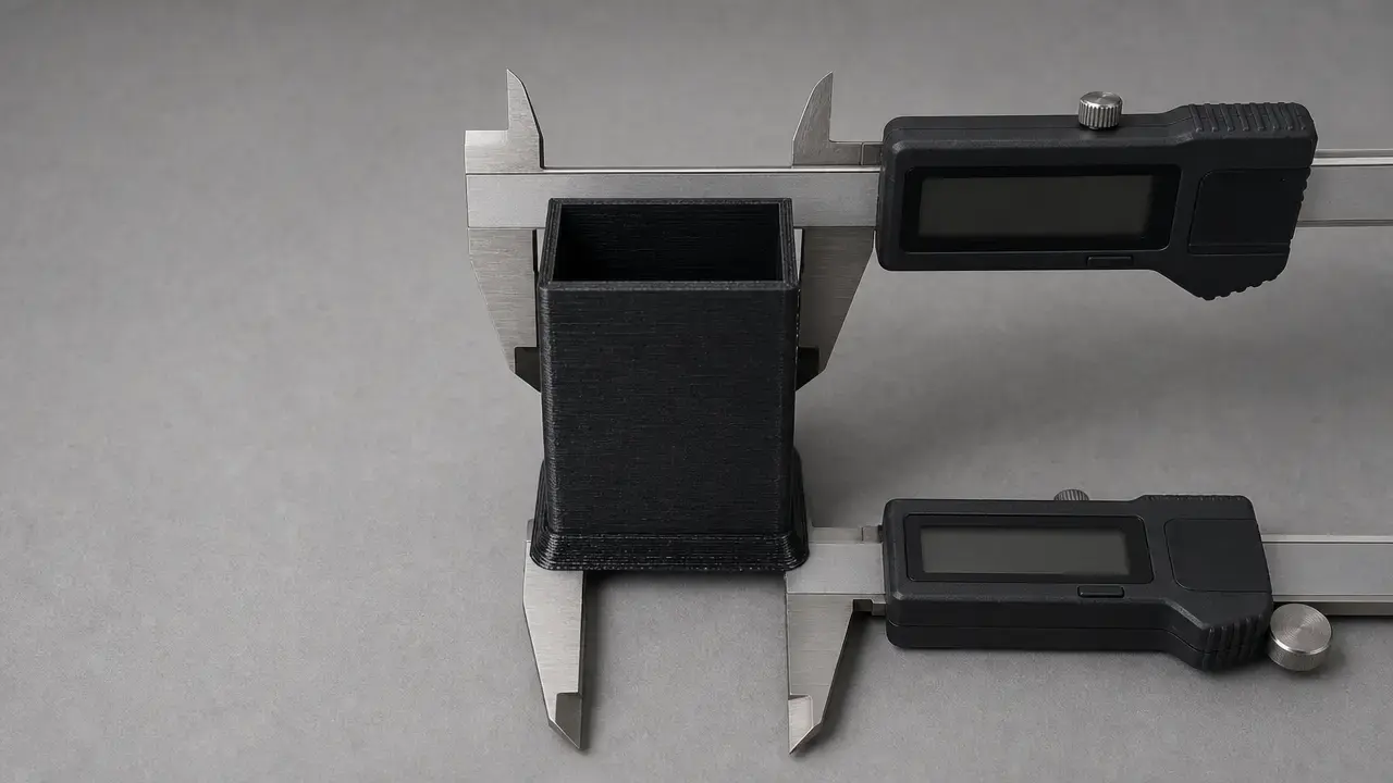

Summary: elephant foot 3d printing
Elephant foot 3d printing is the bottom-edge flare that appears when the first layer, or sometimes the first few layers, end up wider than intended. Prusa describes the basic FFF/FDM case as a squished first layer that becomes wider than it should be, while OrcaSlicer documents compensation across multiple early layers rather than only layer 1. [SRC-01] [SRC-07]
The safest fix order is to correct first-layer conditions first, then use elephant-foot compensation only for any remaining bottom-only error. That matters because elephant foot is different from warping, which lifts upward, and different from global XY oversize, which affects the whole part. The measurement step matters too: compare the width at the very bottom with the width above the flare, then check whether your slicer expects a per-side contour offset or a total-width correction. [SRC-05] [SRC-07] [SRC-11]
What elephant foot is
In filament printing, elephant foot is a bottom-layer dimensional flare: the base of the part prints wider than the model, usually in the first layer and sometimes across the first few layers. Prusa’s explanation centers on the first layer being squished against the heated bed, while OrcaSlicer’s settings and examples show that the effect can extend beyond a single slice. [SRC-01] [SRC-07]
It is not just cosmetic. It changes the actual footprint of the part where assemblies begin, which is why it matters for flat mating faces, snap-fits, sliders, tabs, bosses, holes, slots, and print-in-place parts near the build plate. Prusa explicitly frames the issue as a problem for parts that need precise dimensions or tight fits. [SRC-01]
Why it matters for fits and function
For functional parts, the bottom edge is often the first reference surface that meets another component. If that edge flares outward, the part can start too tight even when the upper walls look correct. That is why elephant foot can affect sliders, snap-fits, tabs, bosses, or any feature placed close to the build plate. Prusa’s guidance is consistent with that interpretation: a first layer that ends up wider than intended becomes a real dimensional problem when a part must fit precisely. [SRC-01]
Symptoms vs similar defects
A true elephant foot usually looks like a lip at the base. The part is widest right at the build plate, then returns closer to nominal size a little higher up. OrcaSlicer is useful here because it treats elephant foot as something that can involve the first few layers, not only layer 1, so the flare may occupy a short bottom zone rather than a single outline. [SRC-07]
The main look-alikes fail in different directions. Warping or corner lift peels upward from the plate, not outward. Global XY oversize affects the part more broadly, which is why Cura and OrcaSlicer separate whole-model XY compensation from bottom-layer elephant-foot tools. [SRC-05] [SRC-07] Localized blobs or zits are isolated surface artifacts, not a uniform base flare.
Quick checks:
- Compare a dimension at the very bottom with the same feature measured several millimeters above the build plate.
- Check whether the flare is only on layer 1 or persists through the first few layers. OrcaSlicer explicitly supports multi-layer elephant-foot compensation. [SRC-07]
- Check whether the effect is uniform across the plate or stronger in one area, which points more toward consistency problems in bed height or leveling. [SRC-07]
- Record the slicer, profile, material, bed surface, initial-layer height, initial-layer line width, initial-layer flow, bed temperature, nozzle temperature, and Z offset so you can compare runs properly. NIST’s test-artifact guidance emphasizes documenting process parameters and remeasuring geometry. [SRC-11]
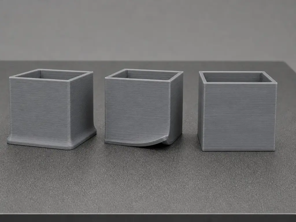
Why elephant foot happens: a cause model you can test
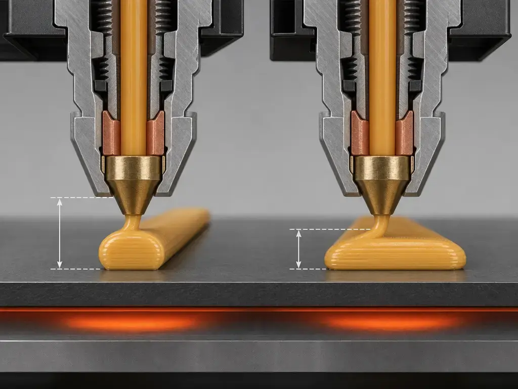
The first contributor is nozzle-to-bed distance. If the nozzle is too close, the first layer is geometrically compressed and spreads outward. Prusa’s Live Adjust Z documentation shows one common sign convention: values start at 0.000, and more negative values move the nozzle closer to the bed. [SRC-03] Prusa’s MINI/MINI+ calibration page also stresses that the number itself is machine-specific, with a commonly seen range of -0.400 to -1.900 on that platform, so copied Z values are not transferable rules. [SRC-02]
The next contributors are commanded geometry and commanded volume, and it helps to keep them separate. First-layer height changes how much the bead is flattened in the available gap. First-layer line width changes the intended footprint directly. First-layer flow changes how much material is delivered into that footprint. Cura’s setting taxonomy supports that split: xy_offset_layer_0 changes first-layer geometry, while Cura 5.2 added Initial Layer Outer Wall Flow, Initial Layer Inner Wall Flow, and Initial Layer Bottom Layer Flow as separate first-layer flow controls that UltiMaker says can reduce elephant’s foot. [SRC-05] [SRC-06] Bambu Studio’s common process JSON also shows separate keys for initial_layer_print_height, initial_layer_line_width, and elefant_foot_compensation, which is another reminder that these are different levers even when they can produce a similar-looking symptom. [SRC-08]
Heat can add to both effects. OrcaSlicer lists weight from material above, thermal expansion, bed temperature that is too high, and inaccurate bed height or leveling as causes; this is best treated as documentation-backed guidance rather than controlled proof. [SRC-07] Independent evidence supports the broader trade-off: Spoerk et al. reported significantly increased adhesion when the bed temperature was set slightly above the material’s glass transition temperature, but that study used a specific setup with a 0.5 mm nozzle, a 0.2 mm first layer, 2 mm³/s flow, 50 mm/min print speed, and bed temperatures from 30 to 120 °C in 10 K steps. [SRC-12] Bed temperature is therefore a balance between grip and softening, not a one-direction fix.
Measure it: from observed flare to a compensation number
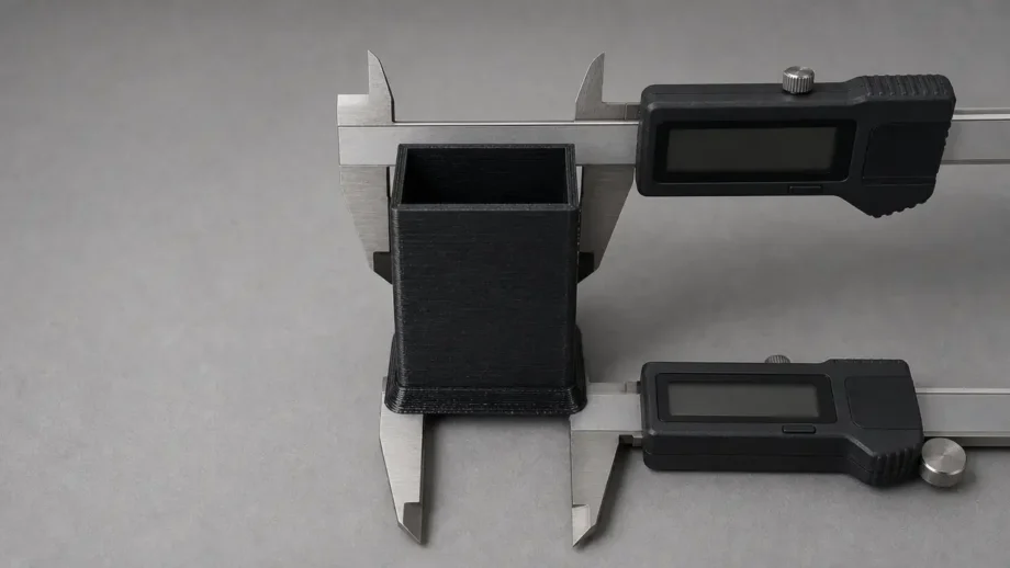
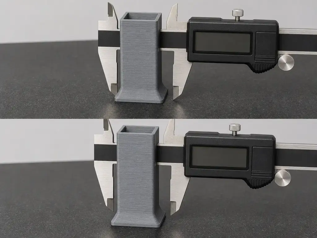
Measure the bottom-only deviation, not general XY accuracy. The goal is to compare the width at the foot with the width of the same feature above the flared zone, then repeat that process after each change. NIST’s additive-manufacturing test-artifact guidance is the right mindset here: document process parameters, measure geometry, compare deviations, and repeat periodically. [SRC-11]
Use one measurement for the width at the foot and another for the width above it. Call them W_bottom and W_above if you want shorthand. The total flare is ΔW = W_bottom − W_above. The slicer value may or may not be that full number. Prusa describes its feature as shrinking or scaling the first layer, while Cura describes Initial Layer Horizontal Expansion as an offset applied to all polygons in the first layer, with negative values used to compensate elephant’s foot. [SRC-01] [SRC-05] If your slicer defines the value as a contour offset, entering the full ΔW can over-correct by ~2×.
- Print a simple straight-walled test part with a flat base. For the test part size, no reliable standard coupon figure found.
- Measure the same outside width at the very bottom (
W_bottom) and above the base flare (W_above). - Compute total flare:
ΔW = W_bottom − W_above. - Start with per-side compensation ≈
ΔW / 2if your slicer uses a contour offset rather than a full-width correction. - Apply that value using the slicer’s own sign convention.
- Reprint, remeasure, and adjust in smaller increments. [SRC-11]
Fix workflow: Z offset vs first-layer flow vs heat
Start with bed cleanliness and repeatable first-layer conditions. Prusa’s first-layer calibration guidance explicitly says to begin with a clean print surface, and the Spoerk paper’s recommendation list also includes cleaning the surface and leveling the bed as adhesion-relevant basics. [SRC-02] [SRC-12] That does not turn this into a full adhesion guide; it just makes elephant-foot changes easier to interpret.
Use visible cues to split the problem. If the first layer looks smeared, fully over-flattened, or difficult to remove, suspect nozzle height first. Prusa’s calibration images distinguish too high, too low, and just-right first layers, and they repeatedly warn that the numeric value means little without visual confirmation. [SRC-02] If the lines are shaped reasonably but the base is still too fat, look next at first-layer line width, first-layer-only flow, or heat retention near the bed. If the effect changes across the plate, OrcaSlicer’s documentation-backed cause list points you back toward bed-height consistency or leveling rather than one global Z-offset number. [SRC-07] Baseline extrusion should be reasonable before you start trimming only the first layer.
Minimum safe sequence:
- Confirm the bed is clean and first-layer consistency across the plate is reasonable. [SRC-02] [SRC-12]
- Set or verify Z offset with a first-layer test, using visual appearance first because the numbers are machine-specific. [SRC-02]
- Confirm baseline flow is reasonable before touching first-layer-only flow settings.
- If adhesion is stable but the base is still oversized, measure
ΔWand convert it to a per-side compensation value if appropriate. - Apply slicer compensation conservatively.
- Reprint, remeasure, and log the change. [SRC-11]
Once the baseline is right, compensation becomes a valid second-order tool. It can remove residual bottom-only error, or it can preserve some deliberate first-layer squish for adhesion while restoring the finished base closer to nominal dimensions. Prusa’s description of elephant-foot compensation as a first-layer shrink tool fits that role. [SRC-01]
Slicer settings for elephant foot compensation
Compensation works by intentionally reducing the bottom footprint so the real printed part, after first-layer squish, lands closer to the CAD size. Prusa describes this as shrinking or scaling the first layer, while OrcaSlicer extends the idea across the first specified number of layers with a documented linear fade. [SRC-01] [SRC-07]
| Slicer | Setting name | Scope / behavior | Practical caveat |
|---|---|---|---|
| PrusaSlicer | Elephant foot compensation | Found under Print settings → Advanced; shrinks the first layer and includes thin-line protection in PrusaSlicer 2.2 and newer. [SRC-01] | Prusa says around 0.2 mm is often a useful starting point for a 0.4 mm nozzle, but that is a Prusa example, not a universal rule. Preview brim gaps can be normal; a real printed disconnect means the value is too high. [SRC-01] |
| Cura | Initial Layer Horizontal Expansion (xy_offset_layer_0) |
Applies an offset to all polygons in the first layer; negative values can compensate elephant’s foot; default 0 mm with a warning range of -1 to 1 mm. [SRC-05] | Because it affects all first-layer polygons, it can also change holes and thin features at layer 0. [SRC-05] |
| OrcaSlicer | elefant_foot_compensation, elefant_foot_compensation_layers |
Applies compensation across the first N layers with a linear fade. Orca’s example shows 0.25 mm over 5 layers, with layer 5 reduced to 0.05 mm. [SRC-07] |
Preview may show a smaller footprint or a disconnected brim even when the printed result is correct. High values may require the Brim use EFC outline option. [SRC-07] |
| Bambu Studio | elefant_foot_compensation in common process JSON |
The common profile JSON shows an example value of 0, alongside initial_layer_print_height 0.2 and initial_layer_line_width 0.5. [SRC-08] |
Treat those JSON values as examples only, because printer and material presets can override them. [SRC-08] |
Cura also separates whole-model xy_offset from first-layer-only xy_offset_layer_0, which helps keep global XY tuning distinct from bottom-only correction. [SRC-05] Its Cura 5.2 article separately introduces first-layer flow controls, which is another reminder that footprint, flow, and temperature should not be collapsed into one setting. [SRC-06]
Do not use compensation first if the nozzle is clearly too low, the first layer is visibly smeared, or the result varies from one side of the bed to another. In those cases, compensation mostly hides a setup error and can create new problems such as weak brim attachment or undercut lower features. [SRC-01] [SRC-07]
Brims, rafts, and design workarounds
A brim preview can look alarming even when the print is fine. Prusa says a gap between the part and brim in preview can be intentional because the preview does not visualize first-layer squish, and OrcaSlicer makes the same point about the footprint appearing smaller in preview. [SRC-01] [SRC-07] The real warning sign is physical, not graphical: if the brim does not connect on the printed part, the compensation is probably too aggressive. Prusa says that directly, and OrcaSlicer adds that high elephant-foot compensation may require the Brim use EFC outline option. [SRC-01] [SRC-07]
If compensation is not the best lever, a small bottom chamfer or a sacrificial feature can move the flare away from a critical mating edge. That approach does not fix the root cause, but it can protect a functional interface when the lower edge must assemble cleanly and you do not want to remove too much first-layer contact area.
Resin terminology note
Resin printing also uses the term elephant foot, but the mechanism is different. Prusa’s SLA guidance says prints made directly on the platform can develop an elephant foot because the first layers are cured and the material expands a bit, and it recommends using a pad. [SRC-04] This article stays focused on FFF/FDM.
Standards and metrology context
Formal standards are helpful for vocabulary and for thinking about geometric capability, but they are not a shortcut to a desktop slicer setting. ISO/ASTM 52900:2021 is Edition 2, published in 2021-11, 28 pages long, and confirmed in 2025. [SRC-09] ISO/ASTM 52902:2023 is Edition 2, published in 2023-08, 40 pages long, and its abstract says it covers test geometries and measurements rather than a specific procedure or machine settings. [SRC-10] In other words, ISO/ASTM 52902 is not a desktop elephant-foot tuning procedure. The practical lesson lines up better with NIST: document settings, measure geometry, compare results, and repeat. [SRC-11]
Practical guidance: choosing the least risky fix
Choose the least risky fix by matching the lever to the symptom. If the first layer is obviously over-squished, start with Z offset. If the base is still oversized after nozzle distance and baseline flow look normal, then reduce first-layer-only geometry or flow, or use compensation for the remaining bottom-only error. Cura’s split between global xy_offset and first-layer-only xy_offset_layer_0 is a good reminder not to use whole-model XY correction for a base-only defect. [SRC-05]
Thermal changes can help, but they are a trade-off because bed temperature affects both softness and adhesion. Spoerk et al. found stronger adhesion near temperatures slightly above the material’s glass transition range in their test setup, so temperature should be treated as a balancing tool, not a blanket instruction to always go lower. [SRC-12] Compensation is most useful when you want to preserve reliable first-layer grip yet bring the finished base back toward nominal size.
Conclusion: elephant foot 3d printing fix checklist
Best practice is simple: calibrate the first layer first, then compensate only the residual bottom-only error. That keeps the change tied to the cause instead of hiding a nozzle-height or first-layer-flow problem behind slicer settings. [SRC-11]
For an elephant foot 3d printing check, keep the sequence practical: confirm the first layer is neither too high nor too low, verify that the extra width is confined to the bottom region, choose the least invasive lever, and log each change before reprinting. If a small base flare remains after calibration, elephant-foot compensation is the finishing tool, not the starting point. [SRC-01] [SRC-11]
FAQ
What is elephant foot 3d printing?
Elephant foot 3d printing is a base flare where the printed part is wider at the bottom than it is higher up. In filament printing, that usually comes from first-layer squish and related heat effects near the build plate. Prusa describes the basic case as a first layer that ends up wider than it should be, while OrcaSlicer supports compensation across the first few layers, so it is better to think of elephant foot as a bottom zone rather than a strictly layer-1-only defect. [SRC-01] [SRC-07]
How do you fix elephant foot in 3D printing without losing bed adhesion?
Start with first-layer calibration, not compensation. Make sure the bed is clean, the nozzle is not too close, and the first layer looks properly formed. If the print adheres well but the base is still slightly oversized, use elephant-foot compensation to trim only the bottom region. That order matters because compensation is useful for residual error or for preserving some deliberate adhesion-oriented squish, but it should not be used to hide a major Z-offset or leveling problem. [SRC-01] [SRC-02] [SRC-11]
What causes first layer squish versus over-extrusion on the first layer?
First-layer squish is mainly a geometry problem: the nozzle-to-bed gap is too small, so the bead is flattened and pushed sideways. Over-extrusion is mainly a volume problem: too much material is being delivered for the intended path. Prusa’s Live Adjust Z examples illustrate the geometry side, and Cura’s first-layer flow controls show that flow is a separate lever rather than the same thing under a different name. [SRC-03] [SRC-06] In real prints, those contributors can stack, which is why a fat base does not automatically mean only one setting is wrong.
How do you calibrate Z offset for the first layer, and why don’t numbers transfer?
Use the printed first-layer appearance as the reference, not somebody else’s number. Prusa’s guidance for the MINI/MINI+ shows that the value is unique to each machine and gives a common range of -0.400 to -1.900 only as a platform-specific example. [SRC-02] Prusa’s Live Adjust Z page also shows one sign convention where more negative values move the nozzle closer, but other printers and firmware can use different conventions. [SRC-03] That is why copied Z-offset numbers are unreliable even when two machines use the same nozzle size.
How do I convert measured flare into an elephant-foot compensation value?
Measure the same outside feature in two places: at the very bottom and above the flare. Subtract the upper value from the bottom value to get the total flare, ΔW. Then check how your slicer defines its setting. Cura describes Initial Layer Horizontal Expansion as an offset applied to all first-layer polygons, which is why many users need a per-side correction rather than the full width difference. [SRC-05] If the slicer expects a contour offset, a cautious first guess is about ΔW / 2, followed by a reprint and another measurement rather than a full one-shot correction.
Cura Initial Layer Horizontal Expansion versus Prusa or Orca elephant-foot compensation: what’s the practical difference?
Cura’s Initial Layer Horizontal Expansion is a first-layer geometric offset applied to all polygons in layer 0, so it can affect holes and thin features as well as outside walls. [SRC-05] Prusa’s feature is a dedicated first-layer shrink tool, with Prusa-specific guidance that around 0.2 mm can be a useful starting point for a 0.4 mm nozzle and with thin-line protection in PrusaSlicer 2.2 and newer. [SRC-01] OrcaSlicer goes further by letting the compensation fade across multiple early layers, which is useful when the flare is not confined to layer 1. [SRC-07]
Related on 3D Mag
- Heat Creep in 3D Printing: Causes, Clogs, Fixes
- 3D Print Warping: Causes and Fixes
- Pillowing in 3D Printing: Causes and Fixes
Sources
The numbered list below matches the in-body citation IDs used in this article.
- SRC-01 — Prusa Help: Elephant foot compensation
- SRC-02 — Prusa Help: First Layer Calibration (MINI/MINI+)
- SRC-03 — Prusa Help: Live adjust Z
- SRC-04 — Prusa Help: Geometrically precise objects (SLA elephant foot note)
- SRC-05 — Ultimaker Cura base definition JSON
- SRC-06 — UltiMaker Learn: Cura 5.2 initial-layer flow controls article
- SRC-07 — OrcaSlicer Wiki: Quality settings precision
- SRC-08 — Bambu Studio common FDM process JSON
- SRC-09 — ISO/ASTM 52900:2021 catalog page
- SRC-10 — ISO/ASTM 52902:2023 catalog page
- SRC-11 — NIST Additive Manufacturing Test Artifact page
- SRC-12 — Spoerk et al. (2018) on bed temperature and adhesion in FFF
- SRC-13 — ATMAT 3D Printing Glossary PDF