
Summary
Delta vs cartesian is not a blanket-winner question. The useful answer is a trade-off between motion geometry, build-envelope shape, calibration burden, moving-mass behavior, frame stiffness, and firmware planning.
Marlin’s configuration material uses four main kinematic families as a firmware example: Cartesian, Core (H-Bot), Delta, and SCARA. That is a reminder that kinematics is the mapping from commanded toolpath coordinates to motor motion. [6] Kinematics determines how commanded XYZ motion is produced, but final print results also depend on mechanics, extrusion, materials, and tuning. [18] [19] Firmware also complicates simple comparisons: in Marlin, G0 is a direct alias for G1 on Cartesians and Deltas, and one nominally linear move may be split into smaller planner moves for kinematics or bed-leveling compensation. [7] Do not equate a slicer speed number with real motion, either. Prusa notes that acceleration and jerk settings affect actual print speed, and small models may never reach target speeds. [16]
How to compare printer kinematics fairly
A fair printer kinematics comparison starts with disciplined vocabulary. ISO/ASTM 52900 provides the additive-manufacturing vocabulary baseline, while VIM guards the measurement terms that often get blurred in printer discussions. [1] [2] Without that separation, “accurate,” “precise,” “high resolution,” and “fast” collapse into one vague ranking. VIM defines measurement accuracy as closeness of agreement between a measured quantity value and a true quantity value, while also noting that measurement accuracy is not itself a quantity and is not given a numerical quantity value. [2]
In plain language, accuracy is about being close to the intended value; precision is about repeated results being close to each other. VIM defines measurement precision as closeness among replicate measurements under specified conditions, and repeatability as precision under repeatability conditions. [2] NIST’s glossary adds the useful shorthand that accuracy refers to a combination of trueness and precision. [3] This matters because a printer can be repeatable but offset, or dimensionally close on one feature and poor on another. Nominal step size, layer height, or microstepping is not the same as measured part accuracy. [2]
- Accuracy: closeness of the measured printed feature to the intended or true value.
- Precision/repeatability: how closely repeated prints or measurements agree under specified conditions.
- Resolution: the smallest commanded or represented increment, not proof of part quality.
- Print speed: extrusion move rate during material deposition.
- Travel speed: non-extruding move rate between features.
- Acceleration: how quickly the motion system changes velocity.
- Usable build envelope: the practical printable region after geometry, probing, clearances, and quality limits.
To compare under matched conditions, use the same material class, nozzle size, layer height, slicer strategy, cooling approach, extrusion calibration state, and measurement method wherever possible. Record firmware limits, acceleration and jerk or equivalent cornering settings, belt or arm condition, bed surface, ambient assumptions, and any compensation features. Then print measured artifacts rather than relying only on specification sheets or slicer previews. NIST’s additive-manufacturing test-artifact guidance says all pertinent process parameters and machine settings used to build the artifact should be documented. [4]
NIST’s test-artifact context is useful because it treats geometric accuracy and surface roughness as primary characterization targets, not marketing labels. [4] The same NIST page identifies the artifact as ASTM work item WK40419 and notes that it is not yet an ASTM standard, so it is better read as a benchmark approach than a universal certification rule. [4] A related NIST Journal of Research benchmark paper on an additive-manufacturing test artifact was published on 2014-10-23, which provides a dated anchor for this measurement-oriented way of comparing machines. [5]
A brief lineage note
Delta 3D printer kinematics inherits its basic logic from parallel-robot design rather than from the box-frame layout associated with many desktop printers. A useful anchor is Reymond Clavel’s EPFL doctoral thesis on a fast parallel robot, dated 1991. [17] Desktop additive-manufacturing comparison culture later leaned more heavily on measured benchmark artifacts than on mechanism labels alone; NIST’s additive-manufacturing test-artifact paper, published on 2014-10-23, is one dated reference point for that shift. [5]
What kinematics means in a 3D printer
In a 3D printer, kinematics is the motion-mapping layer between a requested position in X, Y, and Z and the motors that physically create that position. It is not a consumer brand category or a guarantee of print quality. Klipper describes this separation by noting that, outside its kinematic classes, motion is tracked in Cartesian coordinate space; those classes then convert the generic coordinate system to the hardware-specific movements needed by the machine. [14]
That is why a slicer can output ordinary-looking straight toolpath moves while different machines execute them through different motor combinations. Firmware may also transform or segment a move before it reaches the motors. Marlin documents that, for Cartesians and Deltas, G0 is an alias for G1, and that one linear move can become several smaller planner moves because of kinematics or bed-leveling compensation. [7]
Delta vs Cartesian 3D printer kinematics: the core mechanical difference
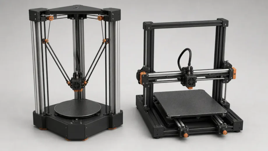
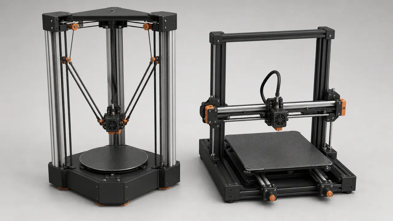
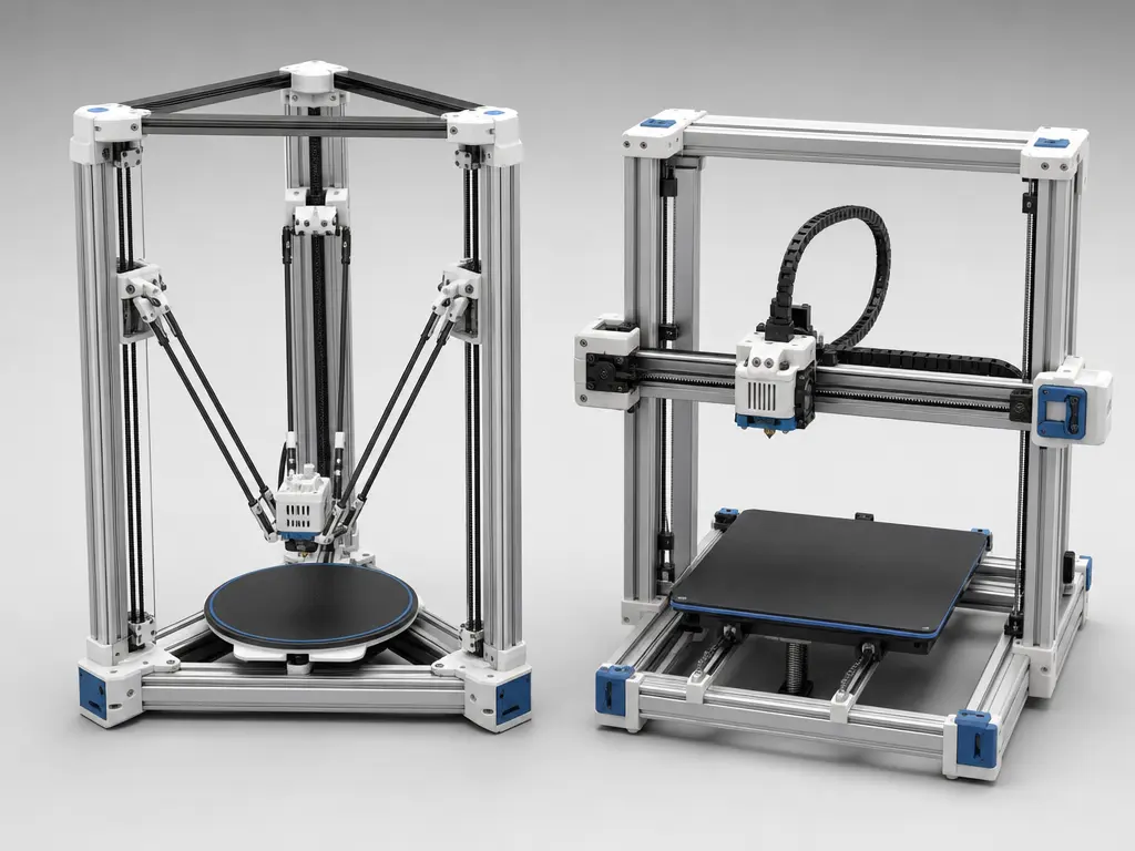
In Cartesian layouts, the commanded X, Y, and Z axes are comparatively direct: on a basic Cartesian, each axis is produced by motion along a corresponding linear axis. [6] [14] Bed-slinger and gantry Cartesians differ in what mass actually moves. A bed-slinger moves the bed and printed part along one horizontal axis, while a gantry Cartesian keeps the bed more stationary and moves more of the toolhead or gantry structure in X and Y. CoreXY still produces Cartesian XY motion, but it uses a distinct belt arrangement rather than a simple one-motor-per-axis horizontal layout. [6]
A linear delta printer uses three vertical towers, with carriages connected by paired arms to a central effector that carries the hot end. Marlin describes Delta motion as three vertical carriages producing XYZ motion in an effector attached by six arms. [6] The requested nozzle position is still expressed in Cartesian coordinates, but the firmware must convert that position into the three carriage heights required by the arm geometry. Klipper describes this general pattern as tracking motion in Cartesian space and converting it through a kinematic class to hardware specifics. [14] For deltas, Klipper also describes the motion with a Pythagorean relationship and notes that lower maximum acceleration and velocity can occur at the extreme edge of the build envelope. [14]
| System | How motion is mapped | Typical moving-mass pattern | Main trade-offs |
|---|---|---|---|
| Cartesian | X, Y, and Z are produced by corresponding linear-axis motion. | Bed-slingers move the part on one axis; gantry designs move more of the toolhead structure. | Mechanically intuitive, rectangular build envelope, artifact behavior depends strongly on axis layout and mass distribution. |
| Linear delta | Three tower carriage heights combine through arm geometry to position one effector. | Light effector moves in XYZ while tower carriages move vertically. | Circular build envelope shorthand, non-linear transform, edge-of-envelope limits can matter. |
The table is not a ranking. It separates motion mapping from the rest of the machine so later comparisons can focus on speed settings, artifacts, calibration, and build-envelope behavior without treating the kinematic label as a complete specification.
Moving mass, realized speed, and why mm/s headlines mislead
A speed number in millimeters per second can mean several different things. Commanded print speed is the requested feed rate for extrusion moves. Travel speed is the requested rate for non-extruding moves. Realized speed is what the machine actually reaches after firmware limits, acceleration, cornering settings, and short segment lengths are considered. Prusa notes that print speeds are affected by acceleration and jerk settings, and small models may never reach target speeds. [16] A printer can also be motion-limited before it is extrusion-limited, or extrusion-limited before it is motion-limited. Marlin’s input-shaping calibration page explicitly warns that high test speeds may exceed what the extruder can handle. [11]
Moving mass shapes how a machine responds when it changes direction. In a bed-slinger, the printed part rides on the moving bed for one axis; Marlin notes that a bedslinger’s moving bed usually has a lower resonant frequency because of greater mass, and its web calibration pattern is marked only for Cartesian printers. [11] A 2025 Ender 3 V2 study identifies the build plate as the Y-axis moving component and reports that Y-axis vibrations can produce ghosting, layer shifts, and deformation, with that axis more vibration-sensitive in that configuration because of the larger moving bed mass. [19] Delta machines move a light effector, but they are not exempt from geometry limits. Klipper notes that extreme-edge delta moves can have lower maximum acceleration and velocity, and it caps stepper acceleration and velocity at 3 times the printer’s configured move limits. [14]
| Metric | What it actually measures | Fair comparison method | What it does not prove |
|---|---|---|---|
| Commanded print speed | Requested extrusion feed rate | Compare the same toolpath and firmware limits | Actual nozzle speed on every feature |
| Travel speed | Requested non-extruding move rate | Separate travel moves from print moves | Printed surface quality by itself |
| Acceleration | Rate of velocity change | Check firmware limits and vibration-sensitive behavior | Universal throughput |
| Moving-mass response | Dynamic behavior of bed, gantry, or effector | Measure artifacts and vibration-sensitive features | Kinematics alone determines quality |
Bowden and direct-drive extrusion are a separate design axis, not a definition of printer kinematics. They matter because they change mass distribution and extrusion behavior. A 2025 moving-mass study states that high direct-extruder weight causes high inertial forces on the print-head assembly, limiting maximum speed and acceleration; in its tested prototype case, a 20 percent head-mass reduction produced about a 2 percent displacement reduction under the tested load. [18]
So the fair question is not which motion system has the largest advertised mm/s number. It is whether the specific printer can maintain controlled motion on the chosen geometry, material, and settings. For a universal delta-versus-Cartesian speed advantage figure, no reliable figure found.
Build envelope and part geometry
For build envelope, the first intuition is shape: many Cartesian printers offer a nominally rectangular box, while many delta printers are described as having a circular bed and cylindrical height. That shortcut is useful, but the usable build envelope is what matters in practice. A rectangular part, long bracket, flat panel, or batch of parts arranged in rows can fit naturally on a rectangular Cartesian bed if the footprint matches the axes. A tall vase, column, or radial object may fit the visual logic of a delta. In delta vs cartesian comparisons, however, nominal volume is not the same thing as printable volume at equal quality.
Delta edge behavior is tied to arm geometry and calibration variables, not just to cylindrical-volume marketing. Klipper notes that moves at the extreme edge of a delta build envelope can have lower maximum acceleration and velocity. [14] RepRap’s delta geometry notes that the reachable area is actually a triangle with bulged sides and is only generally considered circular for simplicity; practical usable area also depends on clearances such as belts and fans. [20] Duet adds that probe points should be well outside the triangle formed by the towers, otherwise calibration cannot accurately distinguish bed tilt from misplaced towers. [15] Match part geometry to the machine’s practical motion region, not only to the advertised dimensions.
Geometries that usually favor each system
- Cartesian: rectangular plates, long bars, box-shaped housings, fixtures, and parts that use most of an X-Y rectangle.
- Delta: centered tall parts, round or radial footprints, spiralized vases, columns, and parts that avoid demanding detail at the outer edge.
Calibration, probing, and firmware-specific complexity
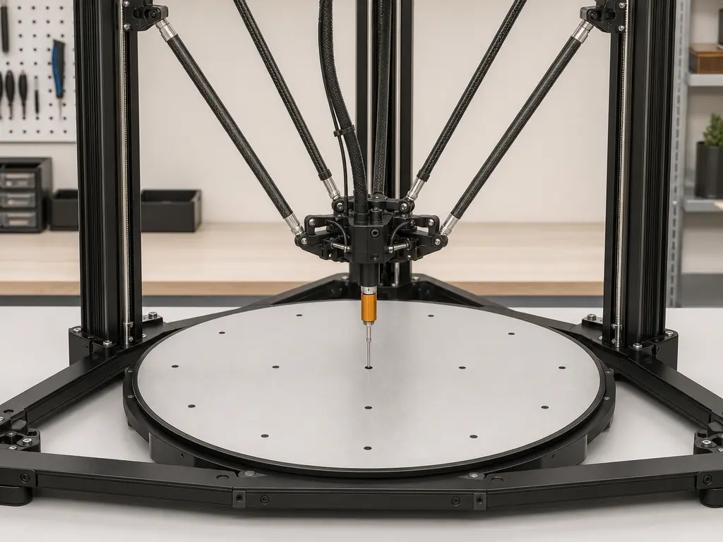
Delta calibration is geometry calibration, not just bed tramming. In Marlin, the M665 delta settings expose A/B/C rod trim, H delta height, L diagonal rod length, R delta radius, S segments per second, and X/Y/Z tower angle trim. [8] Marlin also warns that even small errors in delta geometry values can lead to curved movements and failed prints. [8] Its G33 procedure can calibrate delta height, endstops, delta radius, and tower angles, with point modes including P0, P1, P2, P3, and P4 through P10. [9] That differs from assumptions carried over from other motion-system layouts: Marlin documents that M206 is not available on DELTA and directs delta users to M665 H instead. [10]
Other firmware reaches the same issue with different tooling. Klipper says delta calibration involves tower endstop positions, tower angles, delta radius, and delta arm lengths, and that each parameter has a non-obvious and non-linear impact. [13] Its basic DELTA_CALIBRATE probes 7 bed points. [13] Klipper also recommends manual probing if an automatic probe has bias greater than 25 microns, or 0.025 mm. [13] That matters because probe offset and effector tilt can make the sensed bed plane differ from the nozzle’s actual path; Klipper warns that side-mounted probes on deltas are especially vulnerable to probe-location bias after calibration changes. [13] Duet documents 3-, 4-, 6-, 7-, 8-, and 9-factor delta calibration schemes, with probe-point count at least as high as factor count and up to 32 points. [15]
Duet says 6-factor calibration is best for typical delta builds, endstop switch trigger heights should be within 1 mm, estimated R and H starting values only need to be within about 5 mm, and probe points should be well outside the tower triangle to distinguish bed tilt from misplaced towers. [15] The practical lesson is simple: check what the firmware thinks the machine is before copying setup advice. If someone says auto calibration makes delta easy, qualify that immediately—probe quality, geometry, and firmware model still matter. Even basic reporting is kinematics-dependent; Marlin M115 examples include KINEMATICS:Cartesian and can report work-area bounds when geometry reporting is enabled. [12]
Accuracy, precision, resolution, and print quality in practice
In a delta vs cartesian comparison, “print quality” is too broad to stand in for every measurement. For printed parts, the metrology terms from earlier still apply. VIM defines accuracy as closeness to a true value, precision as closeness among replicate measurements, and repeatability as precision under repeatability conditions. [2] NIST’s glossary adds that accuracy combines trueness and precision. [3] A printer may place repeated holes consistently but slightly undersize them, or produce a visually clean wall while missing a critical dimension. Those are different observations, not one kinematics score.
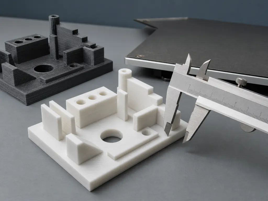
Step size or nominal resolution is not finished-part accuracy. Motor microsteps, belt pitch, tower carriage increments, and layer height describe commanded or discretized motion, while the part reflects extrusion width, material shrinkage, cooling, compliance, calibration, and measurement method. First-layer flatness is not XY dimensional accuracy, either. Klipper makes this distinction explicit for deltas: basic delta calibration sets nozzle-to-bed behavior, but it does not attempt to calibrate X and Y dimensional accuracy; enhanced calibration uses a printed test object and caliper measurement. [13] Klipper’s enhanced example uses a 140 mm diameter printed object and suggests a slow slice such as 40 mm/s. [13]
For Cartesian machines, tendencies depend strongly on subtype. A bed-slinger is not dynamically identical to a gantry Cartesian, because the moving bed carries the growing part along one axis. A 2025 Ender 3 V2 study links Y-axis bed motion in that bed-slinger configuration to ghosting, layer shifts, and deformation. [19] Moving mass is also relevant at the toolhead: a 2025 study links heavier print-head assemblies to higher inertial forces and motion limits, while its reported 20 percent mass reduction and about 2 percent displacement reduction apply only to that tested load case. [18] These observations support measured artifact checks rather than a blanket Cartesian label.
For deltas, dimensional behavior is tightly tied to geometry calibration, probe behavior, and position in the work area. Marlin warns that small delta geometry errors can lead to curved movements and failed prints. [8] Klipper also says probe bias greater than 25 microns, or 0.025 mm, is a reason to prefer manual probing, which matters when nozzle-to-bed calibration is being used as the basis for later motion correction. [13] Delta results can be good in one region and less convincing in another if the model of towers, rods, radius, and probing is off. Print quality is a system-level outcome, not a kinematics-only verdict.
Where each architecture fits best
A delta vs cartesian 3D printer choice usually makes sense when matched to part shape and maintenance style. Delta layouts suit centered, tall, or radial parts that stay comfortably inside the practical motion region. Marlin describes a Delta as three vertical carriages moving an effector through six arms, which is the mechanical basis for the lightweight-effector logic. [6] That fit assumes the user is willing to calibrate geometry carefully and not treat the advertised circular area as fully equivalent to the usable area. [20]
Cartesian machines fit many general-purpose FFF/FDM jobs because their rectangular layout maps naturally to rectangular parts, fixtures, boxes, panels, and parts arranged in rows. Their service path is also straightforward in many desktop contexts: individual axes, belts, leadscrews, beds, and gantries are easier to reason about because motion is visually tied to the machine frame. This does not make every Cartesian machine equivalent; bed-slingers and gantry systems behave differently under load. Speed claims still need caution, because target speed alone is not realized speed when acceleration and jerk settings limit actual motion. [16]
CoreXY deserves only a short orientation here because it is often compared alongside these two. Marlin distinguishes Cartesian, Core or H-Bot, Delta, and SCARA kinematics, and describes CoreXY as a special belt arrangement for XY motion. [6] In practical terms, CoreXY still produces Cartesian X-Y output, but the belt layout and moving-mass distribution differ from a simple bed-slinger or gantry Cartesian frame.
Limits and failure modes to keep in mind
For deltas, the main risks are kinematics-linked and calibration-linked. Klipper notes that delta motion can see lower maximum acceleration and velocity at the extreme edge of the build envelope. [14] Marlin warns that small errors in delta geometry values can cause curved moves and failed prints. [8] Probe behavior is another calibration-linked risk: Klipper treats probe bias over 25 microns, or 0.025 mm, as a meaningful reason to prefer manual probing during delta calibration. [13]
For Cartesians, many limits are subtype-linked rather than universal. In the cited bed-slinger study, Y-axis moving-bed vibration is linked to ghosting, layer shifts, and deformation. [19] That does not describe every Cartesian gantry, but it does show why the moving component matters. Across both families, some limits are system-level or mechatronic: moving mass affects inertial forces and therefore dynamic behavior independently of the printer kinematics label. [18] Extrusion consistency, frame stiffness, cooling, belts, bearings, firmware limits, and maintenance can all dominate a motion-system comparison.
Practical guidance for evaluating a machine claim
-
Interrogate speed and accuracy claims. Ask what machine, material, nozzle, layer height, slicer profile, acceleration, jerk or equivalent cornering settings, and measurement method were used. Short features can miss advertised feed rates because acceleration and jerk settings affect the motion actually achieved. [16] If a vendor or reviewer provides no named machine, material, settings, or measurement method, treat the claim as incomplete. Fair additive-manufacturing comparison requires documented process parameters, documented machine settings, and measured artifacts. [4]
-
Verify the motion-system assumptions. Check what the firmware reports, not only what the frame looks like; Marlin examples can self-report entries such as
KINEMATICS:Cartesianand, when enabled, work-area bounds. [12] For delta machines, confirm whether the calibration being discussed is bed behavior, dimensional behavior, or both, because basic delta calibration does not by itself calibrate X and Y dimensional accuracy. [13] For any printer kinematics comparison, compare under matched conditions and measure the same artifact rather than extrapolating from the motion-system label alone.
Bottom line on delta vs cartesian
The bottom line on delta vs cartesian is that neither wins universally; fit depends on part geometry, calibration tolerance, speed goals, and maintenance appetite. Deltas can suit centered, tall, or radial work, but their geometry model matters, and basic delta calibration handles nozzle-to-bed behavior rather than automatically solving X and Y dimensional accuracy. [13] Their edge-of-envelope moves can also have lower acceleration and velocity than center moves. [14] Cartesians often suit rectangular work and direct mechanical troubleshooting, but subtype, moving mass, firmware limits, and tuning still shape the result.
Treat speed, accuracy, and print quality as measured outcomes, not properties guaranteed by the kinematics label. Target speed alone does not predict realized print speed because acceleration and jerk settings matter. [16] The practical choice is the machine whose motion system, calibration workflow, and build envelope match the parts you actually plan to print.
FAQ
What is the difference between delta and cartesian 3D printers?
Cartesian printers map X, Y, and Z motion through comparatively direct linear axes. Delta printers use three vertical carriages and arm geometry to position one effector. Marlin distinguishes Cartesian, Core, Delta, and SCARA motion systems, and describes Delta machines as using three vertical carriages and six arms. [6]
Are delta printers faster than Cartesian printers?
Not by a universal number; no reliable figure found. Compare commanded speed, acceleration, realized speed, extrusion limit, and part geometry separately. Realized speed depends on acceleration and jerk settings, so short features may not reach the requested feed rate even when the slicer shows a high speed. [16]
Are delta printers more accurate?
Not automatically. Dimensional accuracy, precision or repeatability, and nominal resolution are different claims. VIM separates accuracy, precision, and repeatability, and notes that accuracy is not itself given as a numerical quantity value. [2] Basic delta calibration also does not directly calibrate X and Y dimensional accuracy. [13]
Is CoreXY a Cartesian printer or something different?
CoreXY produces Cartesian X-Y output, but it uses a different belt and mechanical layout from a simple one-motor-per-axis Cartesian frame. Marlin lists Core separately from Cartesian and describes CoreXY as a special belt arrangement for XY motion. [6]
Why can delta printers behave differently near the edge of the build area?
Delta motion depends on geometry transforms from the requested XYZ point to tower carriage heights. As arm angle changes near the perimeter, the effective motion limits can change too. Klipper notes that delta moves at the extreme edge of the build envelope can have lower maximum acceleration and velocity. [14]
Why can an offset probe make delta calibration harder?
A probe may not sense the same point or angle that the nozzle will later use, especially if effector tilt or position-dependent probe bias is present. Klipper treats probe bias greater than 25 microns, or 0.025 mm, as a reason to prefer manual probing in delta calibration. [13]
If slicers send straight XYZ moves, why is delta kinematics still more complex?
The slicer can emit straight-looking Cartesian toolpath moves, but firmware still has to transform them into motor motion. Marlin documents that a nominally linear move may be split into smaller planner moves because of kinematics or bed-leveling compensation. [7]
Sources
- ISO/ASTM 52900:2021 — Additive manufacturing — General principles — Fundamentals and vocabulary
- JCGM 200:2008 — International Vocabulary of Metrology, section 2
- NIST Glossary — Accuracy
- NIST — Additive Manufacturing Test Artifact
- NIST JRES — An Additive Manufacturing Test Artifact
- Marlin Firmware — Configuring Marlin
- Marlin Firmware — G0/G1 Linear Move
- Marlin Firmware — M665 Delta Configuration
- Marlin Firmware — G33 Delta Auto Calibration
- Marlin Firmware — M206 Set Home Offsets
- Marlin Firmware — Input Shaping Calibration Pattern
- Marlin Firmware — M115 Firmware Info
- Klipper Documentation — Delta calibration
- Klipper Documentation — Kinematics
- Duet3D Documentation — Calibrating a delta printer
- Prusa Knowledge Base — Speed settings
- EPFL Infoscience — Reymond Clavel thesis
- Applied Sciences — The Effect of 3D Printer Head Extruder Design on Dynamics and Print Quality
- Applied Sciences — Enhancement of Primary Profile Surface Quality in FFF Printing Through Vibration Monitoring and Active Control
- RepRap Wiki — Delta geometry