Summary
G-code is the line-by-line instruction language that tells a 3D printer what motions and process actions to perform during a print. This article focuses on desktop filament-printing, using standards-friendly material-extrusion terminology rather than additive manufacturing as a whole. In that workflow, the slicer translates a completed print plan into machine instructions the printer can run. [17] [18] [1]
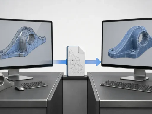
Is it a 3D printing file format? In practice, yes. People often mean the printable file itself, commonly saved as .g, .gco, or .gcode. More precisely, G-code is the language stored inside those files, while STL mainly carries surface geometry, 3MF carries richer model-package information, and a slicer project saved as .3mf can preserve objects, settings, modifiers, and parameters for later editing instead of immediate printing. [19] [22] [23]
What G-code is in 3D printing
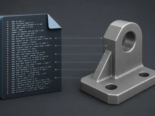
In 3D printing, G-code is the set of machine instructions a printer follows to move, heat, extrude, and manage related print actions. Here, the scope is desktop filament-printing and material-extrusion workflows for plastic materials, not every additive-manufacturing process. A slicer does not simply save the model in another format; once it has planned layers, paths, and process settings, it translates that plan into G-code for the printer to execute. [17] [18] [1]
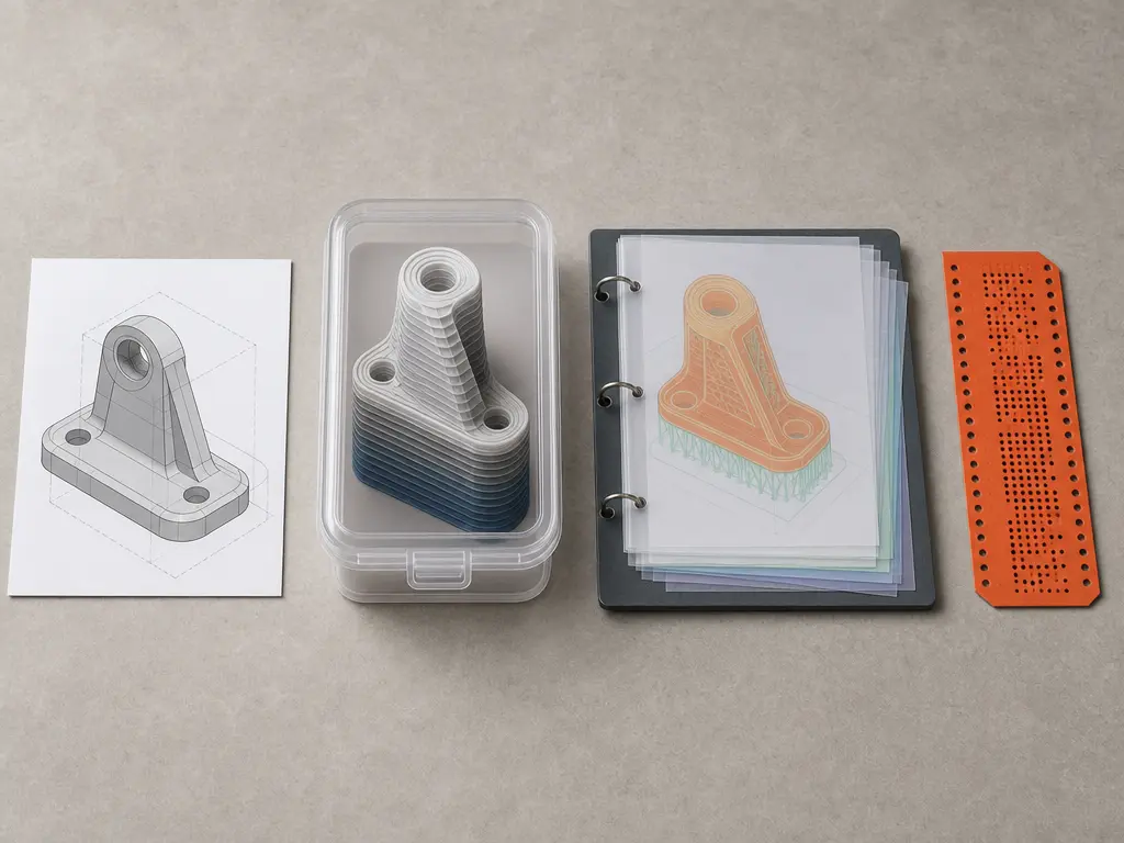
That is why G-code is not interchangeable with model files. An STL mainly stores object geometry as surface triangles, a 3MF file can carry richer packaged model information, and a slicer project may also use .3mf as a complete snapshot containing objects, settings, modifiers, and parameters. G-code sits at a different workflow layer: it is the operational result, usually saved as executable printer instructions in files with extensions such as .g, .gco, or .gcode. Those extensions are useful conventions, but they do not guarantee identical meaning across firmware families or printer setups. [22] [23] [19] [13]
Where G-code came from — and where standardization stops
The name G-code comes from older numerical-control programming lineages rather than from 3D printing itself. A practical reference point is NISTIR 6556, The NIST RS274NGC Interpreter – Version 3, published on August 1, 2000, which describes an interpreter for RS274 code in the NGC dialect. ISO 6983-1:2009 likewise specifies a data format for positioning, line motion, and contouring control systems, and ISO lists that edition as confirmed again in 2025. That ancestry explains some familiar command names, but it does not mean modern desktop-printer firmware implements one uniform language. Current printer behavior is shaped by firmware-specific conventions, extensions, and machine configuration, so legacy standards explain part of the vocabulary, not the full semantics of today’s printers. [15] [16] [13]
How slicers turn models into printer instructions
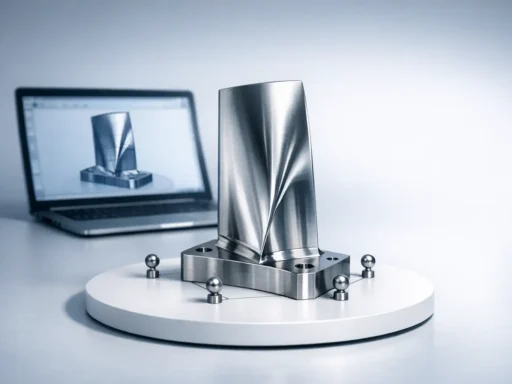
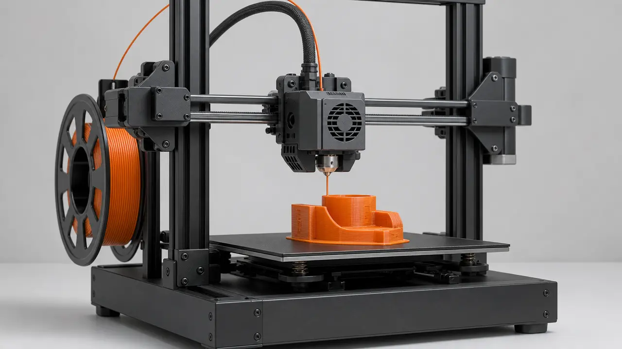
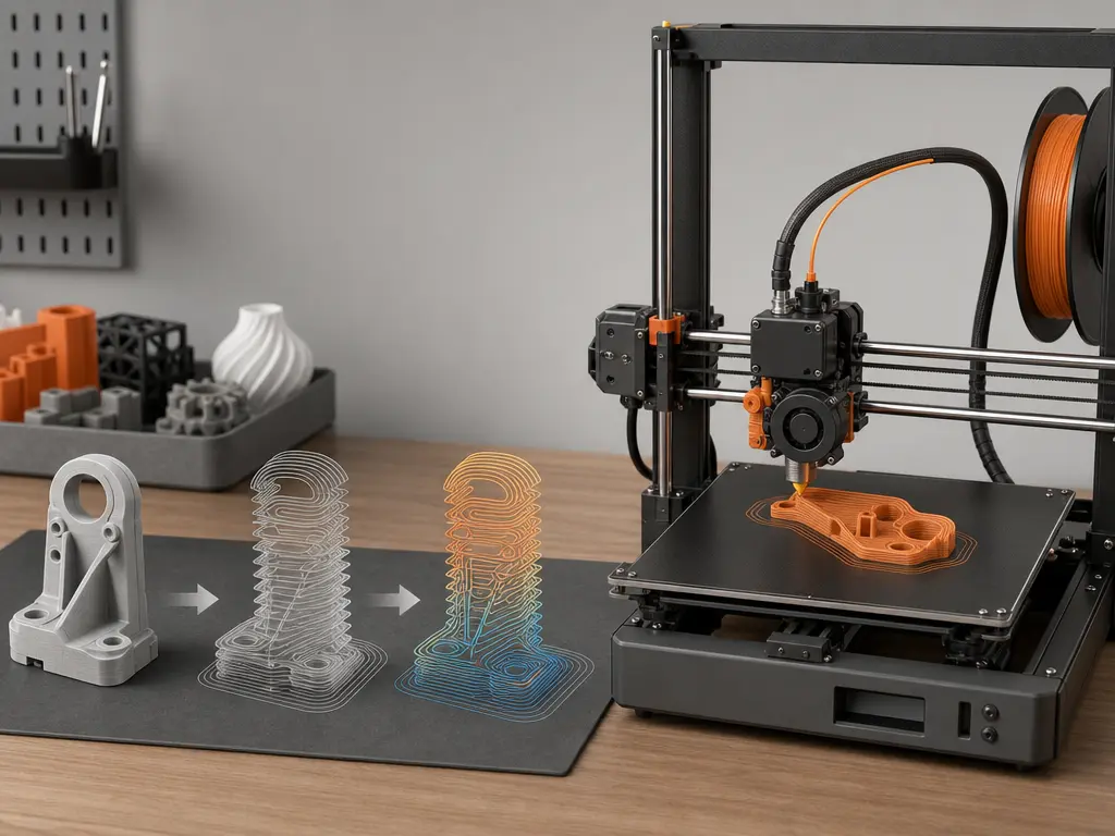
The practical chain is simple: a model, mesh, or project file goes into the slicer; the slicer produces an ordered toolpath plus process parameters; that becomes G-code; firmware interprets it; and the printer carries out motion, heating, and fan control. [1] [13]
Inside the slicer, geometry is divided into layers and then into printable path types such as perimeters, infill, top and bottom surfaces, supports, and non-printing travel moves. The slicer decides their order and assigns process settings to them. CuraEngine documents this mapping directly: a printable path becomes G1, a travel move becomes G0, hotend heating is emitted as M104 or M109, bed heating as M140 or M190, and changes in path properties such as velocity are written with parameters including F. [1]
- Motion commands
- Thermal commands
- Machine-control / support commands
In actual slicer output, those categories appear together in one file. A motion segment may become G0 or G1, thermal state may be set with M104, M109, M140, or M190, and other commands may control fans or report status. Firmware is the layer that interprets commands, with machine configuration affecting final execution. Real workflows also commonly include configurable Start G-Code and End G-Code sequences, so a print file usually contains setup and shutdown behavior as well as the print itself. [1] [13] [14]
G-code commands and what they actually control
G-code commands are the individual machine-control instructions inside a print file. In desktop 3D printer instructions, some mainly describe motion, some control temperature, and others handle support or status tasks often grouped under M-code. The command names below appear across common firmware ecosystems, but support overlaps rather than matching exactly. Klipper, for example, lists G0/G1, M104, M109, M140, M190, M106, M107, M114, and M115, while also stating that its goal is compatibility with common third-party software in standard configurations, not every possible G-code command. [13]
| Command | Typical function | Waits for completion? | Caveat |
|---|---|---|---|
G0 |
Non-extrusion move by common slicer convention. [1] [2] | No. [2] | “Rapid move” is inherited CNC terminology; on Marlin Cartesian and Delta machines, G0 is a direct alias for G1. [2] |
G1 |
Linear move, often with extrusion in slicer output. [1] [2] | No. [2] | F sets the requested movement rate for that move and following moves, in current units per minute. [2] |
M104 |
Set hotend temperature. [3] | No. [3] | Continues without waiting. [3] |
M109 |
Set hotend temperature and wait. [4] | Yes. [4] | With R, Marlin can also wait while cooling. [4] |
M140 |
Set bed temperature. [5] | No. [5] | Continues without waiting. [5] |
M190 |
Set bed temperature and wait. [6] | Yes. [6] | With R, Marlin can wait during heating or cooling. [6] |
M106 |
Set fan speed. [7] | No. [7] | S uses a 0 to 255 range. [7] |
M107 |
Turn fan off. [8] | No. [8] | Dedicated fan-off command. [8] |
M114 |
Report current position. [13] | N/A. [13] | Common status/query command documented by Klipper. [13] |
M115 |
Report firmware information. [13] | N/A. [13] | Common status/query command documented by Klipper. [13] |
A useful distinction is convention versus semantics. Many generators use G0 for travel and G1 for extrusion or printing moves, so humans reading the file often treat the letters as shorthand. But Marlin explicitly notes that on Cartesian and Delta machines, G0 is a direct alias for G1, so “rapid move” is inherited CNC terminology, not a safe universal description of 3D-printer behavior. Familiar command names help you read the file, but firmware still decides how those instructions are executed. [2] [13]
What a slicer actually outputs: toolpaths, coordinates, and parameters
A real print file is a sequence of manufacturing instructions, not just a list of points. Typical contents include:
- startup routine
- motion and extrusion lines
- temperatures and fans
- comments or annotations
- end routine
The core of slicer output is an ordered toolpath expressed as moves, extrusion amounts, and process settings attached to those moves. A line may specify new X, Y, and Z coordinates, an E value for extrusion, and an F value for feed rate. That feed rate is the requested movement rate in current units per minute, not a universal promise of achieved physical speed. CuraEngine also documents that exported G-code can reflect velocity, fan speed, acceleration, jerk, layer thickness, and flow, and that F is added when velocity changes. [1] [2]
Those values are not always self-explanatory unless you know the active modes. G90 sets absolute positioning and G91 sets relative positioning for motion axes. Separately, M82 puts the extruder axis into absolute mode and M83 puts it into relative mode independently of the motion axes. That means the same-looking coordinates or E values can mean different things depending on which modes are active. Comments are common as well, but not universal: PrusaSlicer 2.3 and newer can add annotations such as ;TYPE:, ;HEIGHT:, ;LAYER_CHANGE, ;COLOR_CHANGE, ;PAUSE_PRINT, and ;CUSTOM_GCODE, while Prusa also notes that G-code itself does not contain all the information needed for viewer analysis. [9] [10] [11] [12] [21]
Performance note: readability, sequencing, and why feed rate is not just speed
A G-code file can look readable because it is text, but performance cannot be inferred from isolated lines. Slicer output is an ordered toolpath plus process parameters, so execution depends on sequence, state changes, and firmware interpretation as much as on raw coordinates. The F value is especially easy to oversimplify: Marlin defines it as the requested movement rate for the current move and following moves, in current units per minute. Requested is the key word. A higher F value does not by itself guarantee that the printer will physically achieve that rate, because the actual result still depends on the printer, the firmware, and the surrounding moves. [1] [2] [13]
Is G-code a 3D printing file format?
Yes in practice, but more precisely it is an instruction language usually stored in files that a printer can execute. Calling it a 3D printing file format is reasonable shorthand, as long as you remember that the file contains printer instructions, not just model geometry. [19] [1]
Those files commonly use extensions such as .g, .gco, or .gcode. That matters for storage and workflow, but not as proof of universal command semantics. A file ending in .gcode may still depend on the assumptions of a specific firmware family, machine setup, or slicer workflow. By contrast, the 3MF Consortium describes 3MF as a format that allows design applications to send full-fidelity 3D models to applications, platforms, services, and printers, and its specification page lists the latest Core Specification revision PDF as v1.4.0, with the Core Specification row updated on 2025-02-27. ISO/IEC 25422:2025, Information technology — 3D Manufacturing Format (3MF) specification suite, was published in June 2025. [19] [23] [24]
| File type | Usually contains | Workflow stage | Best use |
|---|---|---|---|
| STL | Surface geometry only. [22] | Model export. [22] | Broad geometry exchange. [22] |
| 3MF | Geometry plus richer packaged model information. [22] [23] [24] | Model or package exchange. [23] | Carrying fuller model data. [23] |
| Slicer project | Objects, settings, modifiers, and parameters in a complete slicer snapshot. [22] | Editable pre-export workspace. [22] | Returning to a slicer job later. [22] |
| G-code | Executable printer instructions. [1] [19] | Final machine-execution stage. [1] | Running the print. [1] |
The practical distinction is that STL and 3MF describe the part or package, slicer projects preserve planning context, and G-code records what the printer should do next. [22] [23]
Why the same G-code is not fully universal
The main reason the same G-code is not fully universal is that shared command names do not guarantee shared behavior. Different firmware families implement overlapping sets of printer instructions, but they may support different subsets or interpret details differently. Klipper states that its goal is to support G-code generated by common third-party software in standard configurations, not every possible G-code command. That alone limits portability. It also explains why any single total command count is unstable: no reliable figure found. [13] [19]
A short Marlin-versus-Klipper contrast shows the problem. On Marlin Cartesian and Delta machines, G0 is a direct alias for G1, so a travel move written with G0 does not necessarily invoke a distinct motion mode. Marlin also documents that M109 can wait during cooling when used with R, and that M190 can wait during heating or cooling with R. Klipper, by contrast, notes that M109 and M190 always wait for the temperature to settle at the requested value. So even when slicers emit familiar text, identical files do not guarantee identical semantics, timing, or machine behavior. Firmware interprets the commands, and the printer’s configuration still affects the final result. [2] [4] [6] [13]
Variants and extensions, including binary G-code
Most desktop-printer G-code is stored as plain text, which makes it easy to inspect line by line. One bounded exception is Prusa’s binary G-code format, .bgcode, which Prusa presents as a storage-focused alternative. In Prusa’s testing, binary G-code reduced average file size by about 70%. Prusa also states that binary export is enabled by default starting with PrusaSlicer 2.7.0, and that firmware support starts with version 5.1.0 for the Original Prusa MINI, MK4, and XL. The tradeoff is straightforward: plain-text G-code is easier for humans to inspect, while binary G-code can save space, but only within the slicer and firmware combinations that support it. [20]
What G-code does not preserve well
G-code sits close to execution, so it often sheds higher-level context that existed earlier in the workflow. By the time a slicer has turned a model into machine instructions, many design-side meanings have been flattened into ordered moves, temperatures, and state changes. That is why a file can be inspectable yet still incomplete as a technical record. Prusa states this directly in the context of visualization: G-code itself does not contain all the information needed for viewer analysis. [21]
That limitation helps explain why richer containers still matter. The 3MF Consortium presents 3MF as a way to carry full-fidelity 3D model information across applications, platforms, services, and printers, and 3MF also has formal ISO/IEC publication status as ISO/IEC 25422:2025, published in June 2025. A slicer project saved as .3mf can go further for workflow continuity by preserving objects, settings, modifiers, and parameters as a complete snapshot. The practical distinction is simple: G-code is usually the file you run, but not usually the best file for preserving everything you may later want to understand, edit, or reproduce. [23] [24] [22]
Practical guidance: how to read a 3D printer G-code file without overreading it
-
Start by identifying the start routine. Real slicer-generated files commonly include configurable Start G-Code and End G-Code sequences, so the first lines may describe setup behavior rather than the print itself. [14]
-
Next, scan for temperature and fan setup, then note any coordinate or extrusion mode lines if they appear before the main motion blocks. That context changes how later coordinates and extrusion values should be interpreted. [9] [10] [11] [12]
-
Read the motion region as ordered slicer output, not as isolated commands. Where present, comments such as
;TYPE:,;LAYER_CHANGE, or;CUSTOM_GCODEcan help human readers, but they are slicer-specific annotations rather than a universal feature of G-code. [21] -
Finish by checking the end routine, then stop short of overclaiming. Familiar command names do not guarantee the same behavior across firmware, because support is aimed at common third-party output, not every possible command. [14] [13]
FAQ
Here are brief clarifications of the main points, including a few boundary cases that matter once you start reading files more closely.
What is G-code in 3D printing?
G-code is the instruction language a 3D printer follows during a job. In desktop filament-printing, it is the execution-stage layer that tells the machine how to move, when to extrude, what temperatures to target, and when to run supporting actions such as fan control. A slicer translates its completed print plan into that instruction output. [1] [18]
What does a slicer output in 3D printing?
A slicer outputs an ordered manufacturing plan, not just the model saved again in another format. That output includes toolpath order plus process settings such as motion requests, temperatures, fan changes, and other print-state instructions. In common desktop workflows, that plan is emitted as G-code. [1]
Is G-code a 3D printing file format?
Yes in everyday use, but more precisely it is an instruction language usually stored in printable files. Those files commonly use extensions such as .g, .gco, and .gcode, but the extension tells you more about storage convention than about guaranteed cross-printer compatibility. [19] [13]
Can I use the same G-code on any 3D printer?
Usually not as a safe general assumption. Different firmware families support overlapping command sets, but overlapping names do not guarantee identical behavior. Klipper explicitly says it aims to support common third-party output in standard configurations, not every possible G-code command, and Marlin’s own documentation shows that even familiar commands like G0 can have firmware-specific behavior. [13] [2]
Why can a file use G0 for travel even though some firmware treats G0 like G1?
Because slicers often use G0 and G1 as output conventions that help humans and software distinguish travel from printing moves. But convention is not the same as execution semantics. Marlin states that on Cartesian and Delta machines, G0 is a direct alias for G1, so the letter choice may be informative without implying a separate motion mode. [1] [2]
How do G90/G91 and M82/M83 change the meaning of the same coordinates and extrusion values?
They change how later numbers are interpreted. G90 and G91 switch motion axes between absolute and relative positioning, while M82 and M83 do the same for the extruder axis independently of the motion axes. So an E value or coordinate triplet only makes sense if you know which positioning modes are active at that point in the file. [9] [10] [11] [12]
Does 3MF replace G-code, or do they serve different stages of the workflow?
They serve different stages. 3MF is for fuller model and package information earlier in the workflow, while G-code is the execution-stage output the printer runs. A slicer project saved as .3mf is different again: it can preserve objects, settings, modifiers, and parameters as a complete editable snapshot rather than as printer-executable instructions. [23] [24] [22]
Sources
- Exporting to G-Code
- G0-G1 Linear Move
- M104 – Set Hotend Temperature
- M109 – Wait for Hotend Temperature
- M140 – Set Bed Temperature
- M190 – Wait for Bed Temperature
- M106 – Set Fan Speed
- M107 – Fan Off
- G90 – Absolute Positioning
- G91 – Relative Positioning
- M82 – E Absolute
- M83 – E Relative
- G-Codes
- Slicers
- The NIST RS274NGC Interpreter – Version 3
- Automation systems and integration — Numerical control of machines — Program format and definitions of address words — Part 1
- Additive manufacturing — General principles — Fundamentals and vocabulary
- Additive manufacturing — Material extrusion-based additive manufacturing of plastic materials — Part 1: Feedstock materials
- G-code
- Binary G-code
- PrusaSlicer G-code viewer
- Saving projects as 3MF
- Specification
- Information technology — 3D Manufacturing Format (3MF) specification suite