Summary
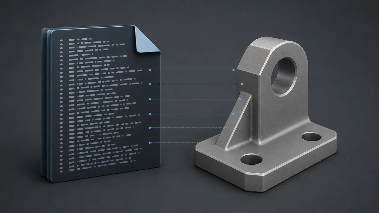
A STEP file is usually a Part 21 exchange file from the ISO 10303 STEP family, used to move product model data between different systems. [1] [4] STEP is the standards family; .step and .stp are usually the file encoding people encounter. [1] [4] [5] In practice, a STEP file is commonly an ISO 10303-21 clear-text exchange file for a particular schema or application protocol, so what transfers depends on the protocol involved and on the behavior of the exporting and importing software, not on the filename extension alone. [3] [4] [13]
What Is a STEP File?
A STEP file is a neutral CAD and product-data exchange file based on ISO 10303. [1] [2] STEP expands to STandard for the Exchange of Product model data, but STEP is the standards family, not just a file suffix. [1] [2]
In everyday use, the file people handle is usually a Part 21 exchange file, the ISO 10303-21 clear-text encoding of the exchange structure, rather than “the whole STEP standard.” [4] That is why STEP is often described as a CAD exchange format or neutral file format for moving model data between software systems. [1] [2] The recommended extensions for files according to ISO 10303 application protocols are .stp and .step, while .p21 is the more general extension label for this exchange style across ISO 10303 and some other EXPRESS-based standards. [5]
Key takeaways
- STEP means the ISO 10303 standards family, not just a filename suffix. [2]
- A
.stepor.stpfile is usually a Part 21 exchange file. [4] [5] - What transfers depends on the application protocol, schema, and software support, not on the extension by itself. [3] [13]
Why STEP Exists
STEP exists because native CAD files do not move cleanly across heterogeneous software ecosystems. [2] A model created in one system may be difficult to reuse in supplier, customer, manufacturing, inspection, or archive workflows if the data stays locked to one vendor’s internal format. [2] Earlier neutral approaches such as IGES helped, but IGES was aimed mainly at geometric exchange, while STEP was designed to cover a wider range of product-related data across the product life cycle. [2]
That broader goal shaped STEP from the start. [2] NIST’s overview of ISO 10303 says development began in 1984, and the first parts were published in 1994. [2] STEP grew as more than a geometry shuttle: it became a standards framework for representing and exchanging product data in a form that could be implemented, tested, and extended. [2] Application protocols are central to that idea because they turn end-user requirements into specifications for scope, exchanged information, testing, and implementation guidance. [3]
How a STEP File Works in Practice
STEP vs Part 21
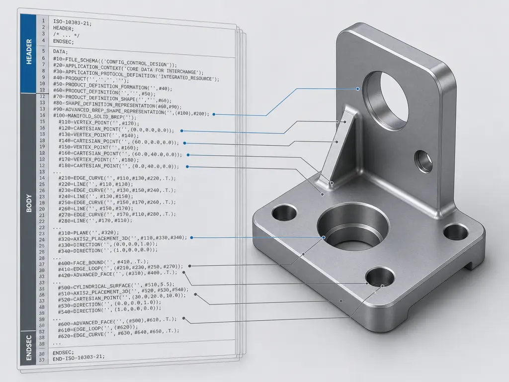
In everyday CAD use, a .step or .stp file usually means a STEP exchange file encoded with ISO 10303-21, commonly called Part 21. [4] Part 21 is not the whole STEP standard; it is the implementation method titled Implementation methods: Clear text encoding of the exchange structure. [4] ISO’s current page lists ISO 10303-21:2016 as Edition 3, published in March 2016 and reviewed and confirmed in 2022. [4] That edition added anchor, reference, and signature sections, support for compressed exchange structures in an archive, digital signatures, and UTF-8 character encoding. [4]
Schemas and application protocols
What makes one STEP file behave differently from another is usually not the extension but the schema and application protocol behind it. [3] [5] A schema is the formal data model, usually written in EXPRESS, that defines what entities and relationships the file can contain. [2] [4] [5] Application protocols, or APs, define the exchange scope, the information to be exchanged, the means of testing, and guidance for implementation. [3] That is why two files both named .step can import differently. [3] One may target AP203, Configuration controlled 3D design of mechanical parts and assemblies; another may target AP214, Core data for automotive mechanical design processes; another may target AP242, Managed model-based 3D engineering. [6] [7] [8]
Why the file is readable but brittle
Because Part 21 files are plain text, you can open them in a text editor and inspect their records. [5] But they use a defined special-purpose syntax, with #-style entity references and schema-dependent meaning rather than ordinary prose. [5] A schema-aware viewer is usually more useful than a basic editor for understanding what the file actually contains. [5] Most users should not hand-edit these files, because changing one record can break references elsewhere or leave the file inconsistent with its schema. [5]
What Data a STEP File Can Contain
A STEP file can carry several kinds of exact and related product data, depending on the application protocol and the exporter-importer path. [8] [13] Within AP242 scope, that includes parts and assemblies plus multiple geometry model types, such as wireframe, geometrically bounded and topologically bounded surfaces, faceted-boundary geometry, boundary geometry, constructive solid geometry, parametric and constrained geometry, 3D tessellated geometry, and 3D scan data. [8] In common CAD terms, that means a STEP workflow can involve wireframe, surfaces, and B-rep or other exact solid representations, not just one generic “solid model file” concept. [2] [8]
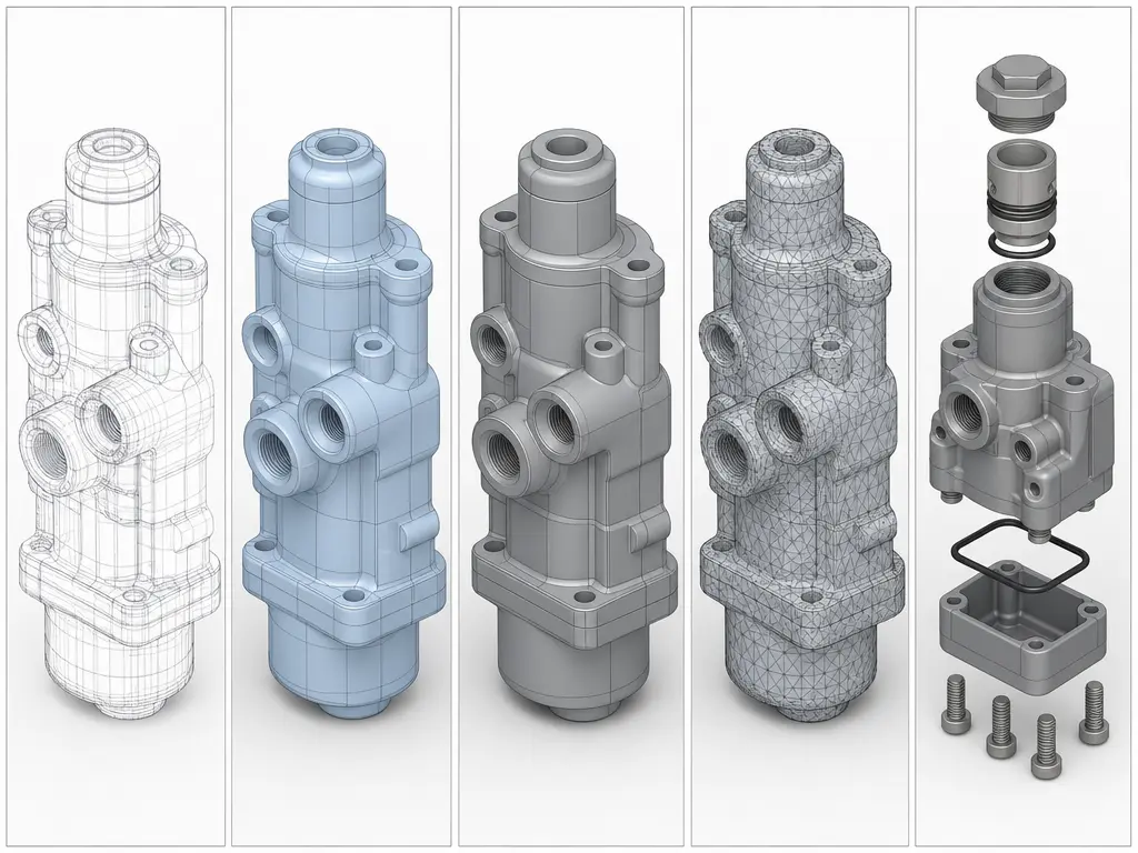
Beyond geometry, STEP can also carry product structure, presentation information, annotated models and drawings, and product manufacturing information in workflows that support it. [8] AP242 scope explicitly includes product manufacturing information, annotated 3D models and drawings, long-term archiving, and mating data. [8] But visible annotation is not a single bucket. [10] Semantic PMI is computer-interpretable and can support downstream CAD, CAM, and CMM processing, while graphic PMI preserves the exact visual appearance of annotations and is not itself computer-interpretable. [10] [11] Validation properties are separate CAD-computed quantities used to check whether transferred data still matches the source model. [10]
The phrase “can contain” matters because standards scope is not the same as real transfer behavior in every software pair. [8] Current vendor documentation shows support varying by direction and object type. [13] [15] Onshape, for example, documents STEP import for parts and assemblies as geometry and face color only, part export as geometry, MBD data, and face color only, and assembly export as geometry and face color only. [13] Autodesk’s AutoCAD help lists translated assemblies, parts, surfaces, solids, and wireframe geometry for its supported STEP import path, while also noting that some formats may not be available in individual AutoCAD-based products. [15] SOLIDWORKS exposes different exporter behaviors by AP label, but those are implementation-specific options, not the definition of the protocol itself. [14] Assembly hierarchy may transfer while mates, constraints, or native design intent do not reappear as equivalent editable behavior across systems, and full feature history is not generally preserved as native behavior after neutral exchange. [13] [17]
Commonly preserved
- Exact geometry such as surfaces and other exact shape representations. [8]
- Part and assembly structure. [8]
- Some visual attributes or annotation-related data, depending on the implementation. [13] [14]
Often lost or implementation-dependent
- Some colors, appearance details, or MBD-PMI content, depending on software direction and options. [13] [14]
- Mates, constraints, and higher-level assembly behavior, even when hierarchy survives. [8] [13]
- Full feature history, parameters, and native design intent. [17]
- PMI semantics, where annotations remain visible as graphics but lose machine-readable meaning. [10]
AP203 vs AP214 vs AP242
AP203, AP214, and AP242 are application protocols within ISO 10303, not simple file-format versions. [3] Historically, AP203 focused on configuration-controlled 3D design of mechanical parts and assemblies, and AP214 focused on core data for automotive mechanical design processes. [6] [7] NIST describes AP242 as the joint successor path created when industry chose to merge AP203 and AP214 rather than keep updating them separately, with AP242 first published in 2014. [9] Today, the ISO pages for AP203:2011 and AP214:2010 show both standards as withdrawn and revised by AP242, while the current reference page is ISO 10303-242:2025 Edition 4, titled Managed model-based 3D engineering. [6] [7] [8]
| AP | Original emphasis | Standards position today | Important caveat |
|---|---|---|---|
| AP203 | Configuration controlled 3D design of mechanical parts and assemblies | Withdrawn; revised by AP242. [6] | Legacy label still appears in translators. |
| AP214 | Core data for automotive mechanical design processes | Withdrawn; revised by AP242. [7] | Legacy label still appears in translators. |
| AP242 | Managed model-based 3D engineering | Current reference point, ISO 10303-242:2025 Edition 4. [8] | Scope extends beyond solids to assemblies, PMI, multiple geometry types, mating data, tessellated geometry, and scan data. [8] |
AP203 and AP214 still matter as legacy translator labels, but AP242 is the current reference point for managed model-based 3D engineering. [8] That does not mean every AP242 export will transfer every category equally well in every CAD pair. [8] [13] It means the protocol scope is broader and more current. [8]
One caution matters here: vendor export limitations do not define protocol scope. [6] [8] For example, SOLIDWORKS documentation says its AP203 option has no color implementation, AP214 exports body, face, and curve colors, and AP242 exports PMI, but that is a SOLIDWORKS-specific exporter description, not a standards-level definition of AP203, AP214, or AP242. [14] [6]
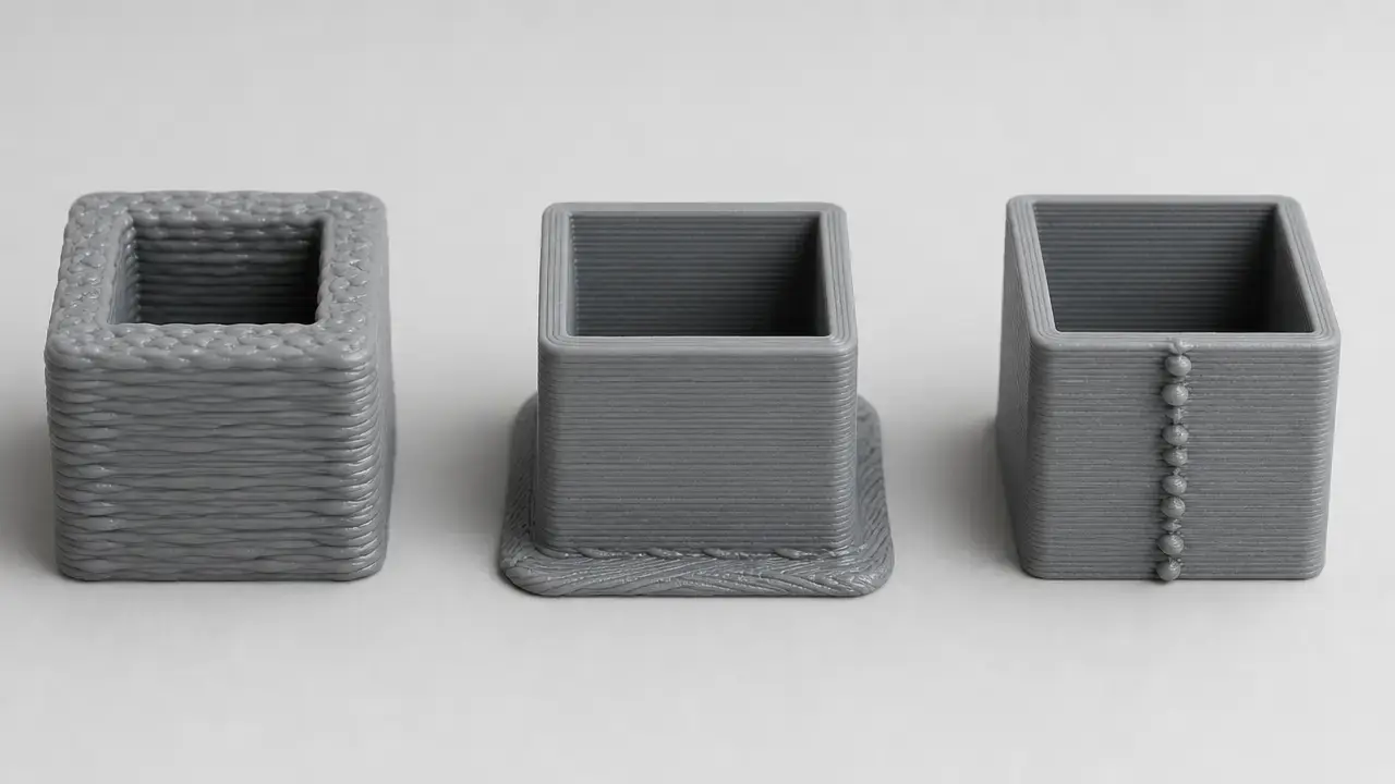
STEP File vs Native CAD Files vs STL
These formats solve different problems, so the useful comparison is what each one is meant to preserve. [5] A native CAD file is usually optimized for editable feature history, parameters, constraints, and design intent inside one software ecosystem. [17] A STEP file, commonly saved as .stp or .step, is a neutral file format for structured exchange of product and geometry data across systems. [5] STL is different again: it describes the surface of an object as a triangular mesh made of facets, which is useful for slicing and other mesh-based workflows but not for rich product-data exchange. [16]
| Format type | Stores best | Best use | Main limitation |
|---|---|---|---|
| Native CAD | Editable feature history, parameters, constraints, and design intent | Ongoing design work in the same CAD ecosystem | Weak for neutral cross-CAD exchange. [17] |
| STEP | Exact geometry and structured product data for interchange | Neutral exchange between CAD, CAM, inspection, and archiving workflows | Often does not preserve full native feature-history behavior. [5] [17] |
| STL | Tessellated surface mesh | Slicing, printing, and simple geometric handoff | No exact analytic geometry or rich product structure. [16] |
In practical terms, STEP is usually the bridge for exact CAD exchange, while STL is usually a print-ready or mesh-oriented handoff format. [5] [16] Calling STEP only a “solid model file” misses surfaces, assemblies, annotations, and other structured data, while calling STL a CAD exchange equivalent misses the fact that it is just a triangular surface mesh. [8] [16]
Where STEP Fits in Manufacturing and 3D Printing
STEP fits best as an exact-model interchange format in broader product data exchange across the product life cycle. [2] It is commonly used for supplier handoff, CAM preparation, inspection and CMM workflows, long-term archiving, and reverse-engineering pipelines that need exact part or assembly structure rather than only a print mesh. [1] [2] [8] AP242 scope explicitly includes assemblies, archiving, multiple geometry types, annotated 3D models and drawings, and scan or tessellated data, while semantic PMI can support downstream CAD, CAM, and CMM use when implementations handle it correctly. [8] [11]
In 3D printing, STEP often appears earlier in the chain than the slicer. [16] A designer may exchange exact geometry as STEP, then convert that geometry into STL or another tessellated representation for print preparation, because slicing software typically works from triangular mesh data rather than from richer product-data exchange structures. [16]
Import, Export, Repair, and Validation
A STEP handoff is a workflow, not a single save action. [10] [11] Export settings, receiving-system support, geometry healing, and validation all affect whether the transfer is good enough for downstream use. [10] [13] [15]
- Export the model from the source CAD system using the intended STEP options and AP scope. [3] [14]
- Import it into the target system. [13] [15]
- Inspect geometry, assembly structure, attributes, and visible annotations. [10] [13]
- Repair or heal gaps, topology issues, or mapping problems if needed. [10] [15]
- Validate the result against expected properties and PMI behavior before approving the handoff. [10] [11]
Validation is more than “the file opened.” [10] NIST distinguishes semantic PMI, graphic PMI, and validation properties for exactly this reason. [10] Semantic PMI is computer-interpretable PMI representation for downstream use, graphic PMI is the exact visual appearance of GD&T annotations and is not computer-interpretable, and validation properties are CAD-computed quantities used to validate import into another system. [10] NIST’s PMI validation project exists because semantic PMI can support direct downstream CAD, CAM, and CMM processing only when the receiving software actually interprets it correctly. [11]
Public test resources exist for this work. [12] MBx says NIST CAD models and derivative STEP files are used by the CAx-IF to test implementations of STEP AP242 in CAD software. [12] NIST’s own validation project measures conformance of CAD software and derivative STEP, JT, and 3D PDF files to PMI standards. [11] Vendor documentation reinforces the same practical point: Onshape shows support varying by import-export direction and object type, and Autodesk notes translated entity support at the product-help level rather than as a universal STEP guarantee. [13] [15] Opening a STEP file successfully does not prove the transfer was complete. [10] [11]
What gets lost in STEP translation?
Neutral exchange usually preserves resulting geometry better than native modeling behavior. [17] What survives depends on the protocol, the exporter and importer, and the receiving system’s support for presentation, structure, and PMI interpretation. [10] [13]
- Missing colors or appearance data in some directions or object types. [13] [14]
- Topology mismatches or healing problems that require repair after import. [10] [15]
- Lost feature history, parametric logic, or native design intent, even when the shape is still usable. [17]
- Degraded PMI semantics, where annotations remain visible as graphics but lose machine-readable meaning. [10]
- Changed assembly relationships, or missing mates and constraints, because native assembly behavior does not necessarily transfer as equivalent editable intent in a neutral exchange. [8] [13] [17]
Current Standards Picture
As of May 16, 2026, the ISO reference page lists ISO 10303-242:2025, Edition 4, titled Application protocol: Managed model-based 3D engineering, with publication dated August 25, 2025. [8] Its published scope covers a broad model-based engineering domain that includes parts, assemblies, archiving, PMI, multiple geometry model types, mating data, and additional downstream-facing categories beyond geometry alone. [8] NIST also says AP242 Edition 4 has now been deployed by all major CAD vendors. [1]
Practical guidance: how to think about STEP before you click export
Choose the format by the job. [3] Use native CAD when the receiver needs the best chance of preserving editability inside the same software ecosystem, use STEP when you need neutral exact-model exchange across systems, and use STL when the goal is mesh handoff for printing. [5] [16] Before export, decide whether geometry, assembly structure, visual appearance, or PMI is the real priority. [3] After import, verify the result instead of assuming equivalence from the file extension or the fact that the model opened. [10]
FAQ
Here are short answers to the questions readers usually ask first.
-
What is a STEP file?
A STEP file is a neutral CAD exchange file used to represent product data between different software systems. [1] [2] In practice, it is usually a Part 21 exchange file from the ISO 10303 family, commonly used to transfer exact geometry and structured product data without relying on one vendor’s native format. [4] [5] -
What does STEP stand for in 3D modeling?
STEP stands for STandard for the Exchange of Product model data. [1] [2] The name refers to the broader ISO 10303 standards family, not just one file suffix, even though users often say “STEP file” when they mean a.stepor.stpPart 21 exchange file. [2] [4] -
Is a STEP file a solid model file?
Often in practice, yes, but that wording is incomplete. [8] A STEP file can represent solids, surfaces, assemblies, and other structured product data depending on the application protocol and the exported content, so calling it only a solid model file leaves out much of what STEP is used for. [8] -
What is the difference between
.stpand.step?
Usually there is no practical content difference between.stpand.step. [5] They are both recommended extensions for files according to ISO 10303 application protocols, while.p21is the more general extension label for this clear-text exchange style across ISO 10303 and related EXPRESS-based standards. [5] -
Can you edit a STEP file?
You can open a STEP file in a text editor because it is plain text, but that does not make it a good file to hand-edit. [5] The syntax is structured for machine interpretation, with entity references and schema dependencies, so most users are better off using CAD import tools or validation tools instead of a plain editor. [5] [10] -
Expert: Does STEP keep feature history, mates, or design intent?
Usually not in the same way as a native CAD model. [17] STEP is strong at transferring resulting geometry and some product structure, but feature history, constraint behavior, mates, and higher-level design intent often do not survive as fully editable native behavior after import into another system. [13] [17] -
Expert: What is the difference between semantic PMI, graphic PMI, and validation properties?
Semantic PMI is machine-readable product manufacturing information with explicit meaning that software can interpret computationally. [10] Graphic PMI is the visible presentation of that information for human viewing and is not itself computer-interpretable. [10] Validation properties are comparison quantities computed by native CAD software to check whether imported data still matches the source. [10]
Sources
- NIST — STEP at NIST
- NIST — Introduction to ISO 10303, the STEP Standard for Product Data Exchange
- NIST — STEP: What Is STEP and How Is It Used?
- ISO — ISO 10303-21:2016
- Library of Congress — STEP-file, ISO 10303-21
- ISO — ISO 10303-203:2011
- ISO — ISO 10303-214:2010
- ISO — ISO 10303-242:2025
- NIST — On Migrating ISO 10303 PMI Models to a Common Core
- NIST — STEP File Analyzer and Viewer
- NIST — MBE PMI Validation and Conformance Testing
- MBx Interoperability Forum — NIST CAD Models and STEP Files
- Onshape Help — Supported File Formats
- SOLIDWORKS Help — Advanced Conversion Options (STEP)
- Autodesk Help — STEP Translator Reference
- Library of Congress — STL (STereoLithography) File Format Family
- NIST-linked scientific PDF — CAD/CAPP Integration using Feature Ontology