Summary
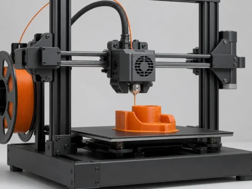
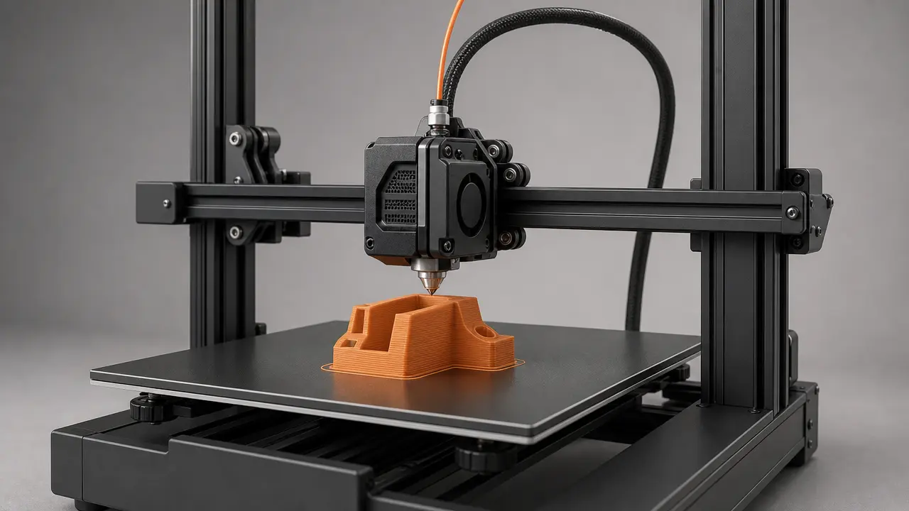
G-code is the sliced instruction output that tells a 3D printer what to do, and this article focuses mainly on desktop FFF filament-printer workflows rather than additive manufacturing as a whole. FFF is the generic process term used here; “FDM” is common shorthand, but FDM is a Stratasys trademark. [14] [18]
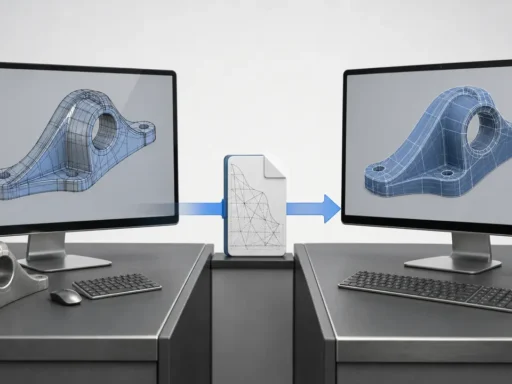
In that workflow, G-code is best understood as printer instructions generated after slicing, not as the original design file. The chain is simple: model data goes into a slicer, the slicer combines that geometry with machine and process settings, and the result is exported as machine-readable toolpath output for firmware to execute. Ultimaker’s workflow documentation classifies .gcode, .gcode.gz, and .ufp as toolpaths, while .3mf appears under project files with a mesh type. Prusa likewise says 3MF is its preferred format and that it is also used to save project files. [13] [16]
What G-code Is in 3D Printing
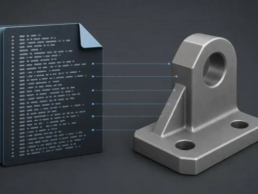
In 3D printing, G-code is a line-by-line set of printer instructions that tells a machine how to move, when to extrude, and when to change process conditions such as temperature. Those instructions are interpreted by firmware, or by a print workflow that ultimately passes them to firmware for execution. That is why calling G-code a plain “3D file format” is incomplete: its main role is not to preserve a model, but to drive a machine through an ordered sequence of actions. In practice, G-code is better understood as a family of related command dialects than as one universal 3D-printing standard. Klipper makes this explicit by framing compatibility around common third-party software in standard configurations, not around supporting every possible command. [11]
That is also why “printer instructions” is a more accurate label than treating G-code as just another design file beside STL or 3MF. The 3MF Consortium positions 3MF as a format for sending full-fidelity 3D models, which makes the contrast clearer: 3MF is model-centered, while G-code is execution-centered. People sometimes use “machine code” casually for G-code, but that is only shorthand, not CPU machine code. A G-code file is better thought of as an instruction script for motion and process control, with meaning that depends on the machine and software context reading it. [2] [11]
Historically, desktop-printer G-code descends from older numerical-control practice rather than appearing from nowhere. The key NIST reference is NIST IR 6556: the current NIST publication entry is titled “The NIST RS274NGS interpreter – version 3:” and dated January 1, 2000, while the downloadable PDF is titled The NIST RS274NGC Interpreter – Version 3 and dated August 17, 2000. Its abstract says the interpreter reads RS274 code in the dialect defined by the Next Generation Controller project, with modifications. That is the right scale of historical claim: modern 3D-printer G-code borrows from older RS274 and NC traditions, but should not be described as one unchanged canonical standard. [1]
How Slicers Generate G-code
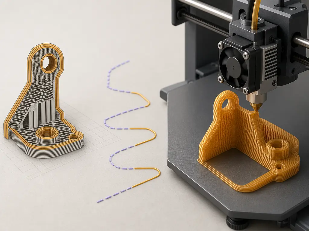
A slicer turns model geometry plus print settings into an ordered toolpath, then exports that plan as printer-readable instructions. In plain terms, the chain is: model or design data → slicer or project settings → sliced toolpath → machine commands. To do that, the software analyzes the shape layer by layer, decides where perimeters, infill, supports, and travel moves should go, and applies machine-specific assumptions from the selected printer profile. CuraEngine describes its role as converting 3D models into G-code instructions, and its export logic maps print paths to G1, travel paths to G0, hotend heating to M104 or M109, and bed heating to M140 or M190. [14]
What the slicer has to decide before export
- layer height
- line width
- speed
- temperature
- supports
- infill
- retraction
- tool changes or machine profile
Once those decisions are made, the slicer writes them out as a sequence of movement commands, extrusion values, and machine-control steps in the order the printer should execute them. A saved slicer project is not the same as that exported output: Prusa describes project 3MF as a complete snapshot containing objects, settings, modifiers, and parameters, while G-code is the generated result of that snapshot. Some workflows may later wrap or translate the output differently, but the central idea stays the same: the slicer has already converted a design and its settings into a toolpath for execution. [15] [14]
G-code vs STL vs 3MF vs Slicer Project Files
A common source of confusion is treating every 3D-printing file as if it served the same role. It does not. STL, OBJ, and STEP are design-side files: they describe geometry, not the exact printer actions needed to make that geometry. By contrast, G-code is the exported instruction stream that tells the machine how to move, extrude, heat, and home. Put simply, source model files describe what the object is, while toolpath output describes how a particular machine should try to build it. [13] [14]
3MF sits between those worlds as a richer container and specification family. The 3MF Consortium positions it as a full-fidelity 3D model format, and its specification page currently lists Core Specification v1.3.0, a latest revision PDF v1.4.0, and Slice Extension v1.0.2. The core specification describes 3MF as an Open Packaging Conventions package that must use a ZIP archive and can contain a model plus optional parts such as PrintTicket data, thumbnails, textures, and other payload components. In practice, slicers may also use .3mf as a project format; Prusa explicitly says 3MF is its preferred file format and that it is also used to save project files. [2] [3] [16]
| Item | Geometry/model data? | Stores settings/assets? | Can it be used to run a print job directly in the target workflow? |
|---|---|---|---|
| STL / OBJ mesh file | Yes | Usually no | No |
| 3MF model/container | Yes | Can include more than geometry | Sometimes, but workflow-dependent |
| 3MF slicer project | Yes | Yes, often heavily | Usually not as the raw instruction stream |
G-code / .gcode |
Toolpath/instructions rather than source geometry | Limited embedded metadata/comments only | Yes, if printer/firmware/workflow are compatible |
| UFP / vendor job package | May bundle toolpath plus assets | Often yes | Workflow-dependent; may require host software or ecosystem support |
Packaged files may be uploaded, unpacked, or streamed by host software rather than parsed identically by every printer. [3] [13]
G-code is therefore not “better STL,” and 3MF is not automatically the same thing as a ready-to-run print file. Ultimaker’s documentation makes this separation explicit by classifying G-code, G-code.gz, and UFP as toolpaths, while listing 3MF under project files with a mesh type. That distinction helps separate files you design with, files you preserve a slicing setup in, and files you actually send toward execution. [13]
Core G-code Commands Readers Will Actually Encounter
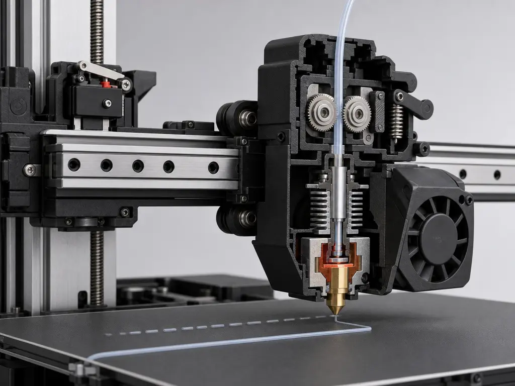
Most everyday print files are built from a small set of movement commands, homing commands, mode-setting commands, and temperature commands. Marlin describes G0 and G1 as queued linear moves, and slicers commonly use G0 for travel moves and G1 for moves that also include extrusion. G28 is another command readers see early in many files, because a machine may begin without knowing where the toolhead is; homing moves the axes toward endstops to establish a known position, and with no parameters Marlin homes all axes. Support and exact behavior can vary by firmware and machine configuration. [4] [10]
Common commands and what they usually do
G0— linear travel move, often used without extrusion. [4]G1— linear move, often used for print moves with extrusion. [4]G28— home axes to establish a known machine position. [10]G90— set absolute positioning mode. [5]G91— set relative positioning mode. [6]M82— set the extruder to absolute mode. [7]M83— set the extruder to relative mode. [7]M104/M109— set hotend temperature and continue, or wait. [8]M140/M190— set bed temperature and continue, or wait. [9]M106/M107— set fan speed, or turn the fan off. [11]
G90 and G91 control axis positioning mode, while M82 and M83 control extruder positioning mode; these are related but not identical states. In Marlin, G90 means absolute positioning, including the extruder unless overridden by M83, while G91 means relative positioning, including the extruder unless overridden by M82. Marlin also states that M82 and M83 control the E axis independently of the other axes, and that G90 or G91 clear that extrusion-mode override. Klipper exposes separate coordinate and extrusion states as well, which helps explain why a G1 command cannot always be interpreted correctly in isolation. [5] [6] [7] [12]
Temperature commands are another place where intent and timing differ. In Marlin, M104 sets a hotend target and continues, while M109 waits before proceeding and can block new commands from the host while it waits. The bed has an equivalent pair: M140 continues, while M190 waits. That is why startup sequences often begin heating early, then insert waiting commands later so travel and preparation steps can happen in between without starting extrusion too soon. Parser state matters here too: Klipper notes that G1 behavior depends on earlier mode-setting and movement history, not just on the single line being read. [8] [9] [12]
Why One Printer’s G-code May Not Work on Another
“G-code” sounds singular, but real compatibility depends on firmware dialect and parser behavior. Klipper explicitly states that supporting every possible G-code command is not its goal, so a file that works on one machine may call commands, parameters, or macros another machine does not recognize. Even familiar movement commands are not identical everywhere: Marlin says that on Cartesian and Delta machines G0 is and must be a direct alias for G1, while SCARA behavior can differ. RepRap’s secondary documentation adds another interoperability detail by noting current RepRapFirmware usage where M83 makes extrusion relative, but G91 does not itself make extrusion relative. Klipper also exposes separate parser states for axis coordinates and extrusion, reinforcing that interpretation depends on prior commands, not just the current line. [11] [4] [19] [12]
Hardware assumptions matter just as much. A sliced toolpath may presume a certain bed size, printable height, nozzle diameter, tool count, and machine geometry. It may also assume a particular origin convention and startup routine. Homing is a simple example: until a homing command establishes a known position, the machine may not know where the toolhead actually is. A file prepared for one printer’s travel limits or multi-tool arrangement can therefore be mechanically unsuitable for another, even if both accept broadly similar commands. [10]
Why compatibility is conditional, not binary
- firmware dialect
- kinematics
- build volume
- nozzle/tool assumptions
- origin/homing conventions
- material/temperature profile
- start/end macro expectations
Process assumptions add another layer. A file may embed temperatures, speeds, retraction behavior, and startup or shutdown sequences tuned for one material and one machine profile. Some workflows also package toolpaths instead of relying on raw text interpreted identically everywhere: Ultimaker classifies UFP as a toolpath artifact, and Prusa’s .bgcode support depends on PrusaSlicer 2.7.0 plus compatible firmware, with Prusa noting compatibility caveats for some external control software such as OctoPrint. Portability is not all-or-nothing; it improves when machine, firmware, material profile, and workflow expectations match closely. [13] [17]
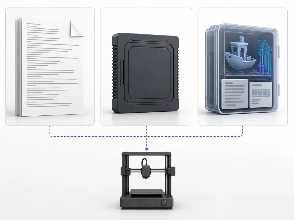
ASCII G-code, Prusa Binary G-code, and Packaged Job Files
Plain-text ASCII G-code is the everyday default mental model: a line-by-line instruction stream that tells a printer where to move, when to extrude, and when to change machine state. That makes it different from packaged workflow files, which may wrap instructions together with thumbnails, metadata, or other payload parts. In the broader file-format landscape, 3MF is officially positioned as a full-fidelity model and container format, and its specification family includes a Slice Extension for 2D sliced model data in a 3MF package. The core 3MF specification also describes 3MF as a ZIP-based package that can contain multiple related parts rather than acting like a raw instruction stream in the way ordinary G-code does. [2] [3]
Prusa documents .bgcode as a binary G-code implementation. Prusa says its own testing shows about 70% average size reduction, that support is enabled by default from PrusaSlicer 2.7.0, and that on the Original Prusa MINI, MK4, and XL it requires firmware 5.1.0 or newer. Do not treat this as proof of one universal binary G-code standard. Ultimaker’s documentation, meanwhile, classifies UFP as a toolpath or workflow artifact distinct from project files such as 3MF. The useful distinction is between raw instruction streams, implementation-specific encodings of those streams, and package-style workflow files that may carry more than just executable toolpath data. [17] [13]
What G-code Is Used for in Practice
In practice, G-code is the slicer output people actually send to a printer after previewing a planned toolpath. A common workflow is to load a model, choose process settings, inspect layers, export the resulting printer instructions, and then upload or stream that file to the machine or a print-management platform. Some platforms explicitly distinguish this toolpath stage from model upload: Ultimaker lists G-code, G-code.gz, and UFP as toolpaths, while noting that uploaded STL files are not cloud-sliced there. [13]
G-code is also used for inspection, troubleshooting, and limited manual adjustment. People read start sequences, heating commands, homing steps, and suspicious movement lines when diagnosing failures. They may insert or modify commands for calibration or workflow-specific macros, but those edits are risky if the file’s state is misunderstood. Klipper makes that explicit: a G1 move depends on parser state established by earlier commands, including coordinate and extrusion modes. A saved project file is safer for repeatable regeneration, because it preserves objects and settings so the same G-code can be produced again later instead of being hand-edited line by line. [12] [15]
Performance and Precision: What G-code Does and Does Not Guarantee
A G-code file defines intended toolpath and process actions: movement commands, extrusion steps, temperatures, and other printer commands. That is necessary for printing, but it does not by itself guarantee dimensional accuracy, surface quality, adhesion, or successful execution. The file can specify where the machine should go, yet the real outcome still depends on how firmware interprets those instructions and how the physical printer follows them. Marlin also notes that slicers tend to override firmware feedrates, which is a reminder that generated instructions and machine behavior interact rather than acting independently. [4]
Execution quality is also state-dependent. A printer may not know its true position until it is homed, and firmware support is selective rather than universal across every possible command. In practice, that means the same nominal toolpath can behave differently depending on homing, machine setup, firmware features, and the assumptions built into the slicing profile that produced it. [10] [11]
Practical Guidance: How to Read a G-code File Without Getting Lost
-
Start at the top and read in execution order. Look first for startup actions such as homing, because the printer may not know its initial position until a homing command establishes it. Then check heating commands: in Marlin,
M104sets hotend temperature and continues, whileM109waits;M140sets bed temperature and continues, whileM190waits. After that, scan the movement commands to see when travel changes into extrusion, and finish by reading the shutdown sequence rather than jumping straight to the middle. [10] [8] [9] [4] -
Before editing any line, identify the machine state that line will inherit. Parser state affects later
G1behavior, so coordinate mode and extrusion mode matter as much as the command itself. Check whether the file is using absolute or relative axes, and whether extrusion is controlled byM82orM83. In Marlin,G90andG91also clear the extruder-mode override, so assumptions can flip after later commands. Also inspect prior E values and any start or end macros. A syntactically valid edit can still cause wrong motion or wrong extrusion if that context is misunderstood. [12] [7]
Research and Standards Context
In current 3D-printing practice, G-code sits inside a living ecosystem rather than a single fixed file-format story. Firmware projects document overlapping but non-identical command sets, and slicers target those environments with implementation choices of their own. CuraEngine, for example, states that it only implements G-code output, while other formats such as X3G are handled elsewhere in the software stack. That makes “G-code 3D printing” less a single universal language than a family of interpreted instruction streams. [11] [14]
Alongside those line-based streams, richer containers continue to evolve. The 3MF Consortium’s specification page lists Core Specification v1.3.0, a latest revision PDF v1.4.0, and Slice Extension v1.0.2, showing an actively versioned standards ecosystem. At the same time, packaging can remain vendor-specific: Prusa’s .bgcode is a current implementation-specific example, not a universal replacement for text G-code or 3MF-based workflows. [2] [17]
What to Remember About G-code
G-code is the sliced machine output of a 3D-printing workflow: a toolpath file of printer instructions generated from a model plus process settings, not the original 3D model itself. Slicers such as CuraEngine convert model information into executable commands for motion, extrusion, and machine control, but the resulting file is not universally portable because command support and interpretation vary across firmware and printer setups. [14] [11]
FAQ
What is G-code in 3D printing?
In 3D printing, G-code is the instruction output a slicer generates from a 3D model and print settings. Instead of storing the original geometry as a design file does, it tells the machine what to do: move to coordinates, extrude material, set temperatures, and run other printer commands in sequence. CuraEngine, for example, explicitly describes its role as converting 3D models into G-code instructions. [14]
Why is G-code called printer instructions?
It is called printer instructions because the file is written for execution by firmware, not for editing the model itself. Typical lines command linear moves, travel moves, heating, homing, and related machine actions. In common FFF workflows, slicers map extrusion paths to movement commands such as G1 and non-print travel to G0, so the file functions as an action list the printer follows step by step. [4] [14]
Is G-code the same as STL or 3MF?
No. STL and 3MF are primarily model- or project-related formats, while G-code is toolpath output for printing. Ultimaker’s documentation distinguishes toolpaths such as G-code, G-code.gz, and UFP from project files such as 3MF, and Prusa describes 3MF as a project snapshot that can preserve settings for regenerating the same output later. So “G-code vs STL vs 3MF” is really a difference in workflow role, not just file extension. [13] [15] [16]
Can one G-code file work on any 3D printer?
Usually not reliably. A G-code file may assume a specific printer size, nozzle, temperatures, extrusion calibration, start sequence, and firmware behavior. Klipper explicitly notes that supporting every possible G-code command is not a goal, which is a useful reminder that compatibility is selective rather than universal. Even when two printers both accept “G-code,” they may differ enough in supported commands, defaults, and macros to make one file unsafe or unusable on the other. [11] [13]
What’s the difference between G90/G91 and M82/M83?
G90 and G91 set axis positioning mode: absolute or relative coordinates for motion. M82 and M83 set the extruder’s positioning mode: absolute or relative extrusion values. Marlin documents these as separate controls, while also noting interactions such as G90 or G91 clearing extrusion override behavior. Klipper likewise lists the extrusion commands separately from the axis-positioning commands. So the short version is: G90/G91 are about where axes move, while M82/M83 are about how extrusion values are interpreted, with firmware-specific nuances. [5] [6] [7] [11]
Why can manual G-code edits break a print even when the command looks valid?
Because a command is interpreted in the context of parser state created by previous commands. Klipper warns that G1 depends on parsing state set by M82, M83, G90, G91, G92, and previous G1 commands. A manual edit can therefore fail if it assumes the wrong coordinate mode, the wrong extrusion mode, an unhomed machine state, or ignores slicer-generated start and end macros. The line may be syntactically valid but still wrong for the machine’s current state. [10] [12]
What is the difference between plain-text G-code, Prusa .bgcode, and UFP?
Plain-text G-code is the familiar line-by-line instruction file many printers and host tools read directly. Prusa’s .bgcode is an implementation-specific binary form, not a universal binary-G-code standard, and Prusa notes both firmware requirements and compatibility caveats with some external control programs. UFP, by contrast, is treated in Ultimaker’s workflow as a toolpath package format alongside G-code and G-code.gz, rather than as a general replacement for all G-code everywhere. [13] [17]
Sources
- NIST — NIST IR 6556 publication entry; downloadable PDF ; PDF
- 3MF Consortium — Specification page
- 3MF Consortium / GitHub — 3MF Core Specification
- Marlin — G0/G1 Linear Move
- Marlin — G90 Absolute Positioning
- Marlin — G91 Relative Positioning
- Marlin — M82 / M83 ; M83
- Marlin — M104 / M109 ; M109
- Marlin — M140 / M190 ; M190
- Marlin — G28 Auto Home
- Klipper — G-Codes
- Klipper — Status Reference + Command Templates ; Command Templates
- Ultimaker — Digital Factory API FAQ
- Ultimaker — CuraEngine repository + Gcode Export wiki ; Gcode Export
- Prusa — Saving projects as 3MF
- Prusa — Supported file formats
- Prusa — Binary G-code
- Stratasys — Legal & Terms
- RepRap Wiki — G-code