Summary: What Is Z Banding? (And Is It Really Z Banding?)
Z banding is a visible surface artifact on the vertical walls of an FFF/FDM print, usually seen as repeated horizontal lines, bands, or waves. It is a workshop troubleshooting term, not a standards-defined consumer defect category. [1] [3]
Many users call any wall blemish z banding, but a seam, ringing, wet-filament defects, vertical fine artifacts, or normal layer stepping can look similar at first glance. [7] [8] [11] [15] The more useful question is whether the pattern repeats with Z-axis motion at a fixed height interval. Wraparound bands that reappear at the same heights on different faces point toward a periodic machine or process effect, while one vertical scar suggests a seam and corner-adjacent echoes suggest ringing. [3] [4] [7] This article treats z banding as a pattern to classify by repeatability, spacing, and location before any fix is attempted. [3] [22]
Quick Triage: What the Pattern Tells You
Start with pattern recognition, not teardown. Bed mesh and first-layer tools can help the bottom of a print, but they do not repair whole-height mechanical or electrical faults, so the shape and position of the marks matter from the start. [9] [10]
- Regular, height-repeatable bands on multiple faces — suspect a periodic Z-motion or repeat-distance issue first. [3] [22]
- Random thickness changes, zits, blobs, bubbling, or smoke during extrusion — suspect extrusion consistency or wet filament first. [4] [11]
- A single vertical line — suspect a seam or start-stop artifact, because each perimeter loop must start and end somewhere. [8]
- Echo lines after corners — suspect ringing or ghosting from mechanical vibration after quick direction changes. [7]
- Marks limited to the first layer or bottom few layers — suspect Z-offset or bed-compensation territory, not classic z banding. [9] [10]
Treat those buckets as provisional. A single print can show more than one artifact at once, so the next step is to check whether the pattern stays locked to height, follows a seam path, or clusters near corners and speed changes. [4] [7] [8]
Z Wobble vs Z Banding: What Is the Difference?
When people compare z wobble vs z banding, the most practical distinction is this: z banding is the visible result on the print, while z wobble is one possible cause family behind that result. [3] Standards help with general additive-manufacturing vocabulary, but they do not create a consumer defect taxonomy for terms like z banding or z wobble. [1]
| Artifact | What you see | Most common mechanism | Fast check |
|---|---|---|---|
| Z banding | Repeating horizontal bands or waves on vertical walls. [3] | A periodic motion or process error that repeats with height. [3] [4] | Do the bands recur at the same heights? |
| Z wobble | A banding pattern tied to screw rotation or carriage motion. [3] | Misalignment, bent lead screw, coupler issues, or constrained Z motion. [3] | Does the pattern behavior suggest a repeat-distance link? |
| Normal layer stepping / layer lines | Even staircase texture, especially on sloped surfaces. [1] | Expected layer-by-layer geometry from additive deposition. [1] | Is it uniform and consistent with the chosen layer height? |
| Z seam | One vertical scar or line. [8] | Perimeter start/end location. [8] | Does the mark stay in one vertical path? |
| Ringing/ghosting | Echoing ripples after edges or corners. [7] | Mechanical vibration after quick direction changes. [7] | Do the ripples appear next to sharp features? |
| Under-extrusion | Missing material in the layers. [14] | Insufficient flow or interrupted feed. [14] | Are sections of material visibly absent? |
| VFA | Fine vertical micro-lines on smooth walls. [15] | Microscopic repeating imperfections at the same point in each layer. [15] | Are the lines subtle, optical, and vertical rather than wraparound? |
Use the table as a filter, not a verdict. VFAs are a good example of why naming too early causes confusion: Prusa describes them as microscopic imperfections that repeat at the same point in each layer, creating vertical lines that may be visible from about 10 µm, with the worst examples in that article around 40 µm peak-to-valley. [15] That is a different pattern from full-wall horizontal banding, even though both may be described loosely as “lines on the print.” [3] [15]
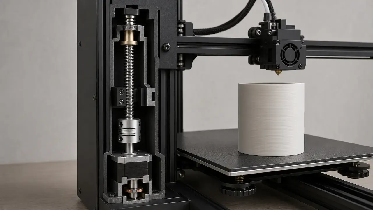
The Mechanics Behind Z Banding (Without Mythology)
Z banding appears when some machine or process variable repeats in a way that shows up on the wall at predictable heights. In practice, the visible pattern can be a stack of motion error, extrusion variation, temperature variation, slicer behavior, and machine rigidity rather than one universal fault. [4] [5] [6] [7]
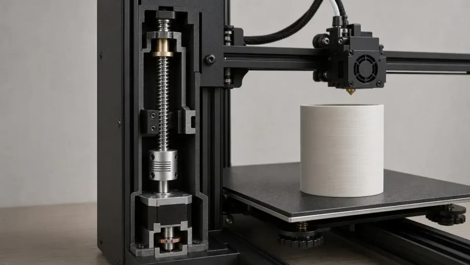
- Z-axis mechanical motion.
- Extrusion consistency.
- Thermal stability.
- Slicer/firmware behavior.
- Frame/gantry rigidity.
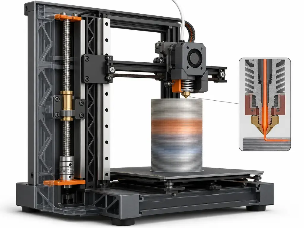
That is why a single-cause story is usually too simple. A constrained or misaligned Z path can create repeating height errors, while inconsistent flow can make one layer wider than the next without any true Z-axis fault. Simplify3D gives an illustrative example: a 5% filament diameter variation could change extruded width by as much as 0.05 mm, which is enough to leave visible side-wall lines. [4] The same source also treats temperature cycling as a possible contributor and uses about ±2 °C as a troubleshooting guideline for a properly tuned printer, with larger variation as a reason to consider PID recalibration. [4] Slicer behavior can add its own lookalikes, such as cooling slowdowns that change surface appearance or make vibration more visible on certain layers. [15]
Pressure-control tools belong in the extrusion bucket, not the geometry bucket. Klipper says typical pressure advance values are between 0.050 and 1.000, and that if no significant improvement appears up to 1.000, pressure advance is unlikely to help. [5] Marlin’s Linear Advance uses a K value with units of mm/mm/s, which also targets extrusion-pressure behavior rather than bent screws or Z binding. [6] Architecture still matters: bed slingers, CoreXY machines, cantilever Z systems, dual-Z designs, and belted Z layouts can show similar-looking surface symptoms through different mechanisms, which is why machine layout should be noted before blaming one part. [12]
Repeat Distance: Turning “It Looks Wavy” Into a Testable Hypothesis
The most useful diagnostic move is to measure or estimate the vertical spacing between repeated bands and ask whether it stays constant. If it does, you have a periodic pattern that can be compared with the repeat distance of the Z drive or with another recurring process effect. Simplify3D explicitly notes that side-wall lines often appear cyclical, while Thomson explains the screw terminology that makes this comparison meaningful. [4] [22] For a screw-driven Z axis, lead is the key concept because it is the distance the nut travels in one revolution of the screw. Pitch is only the distance between thread lands, and for multi-start screws the lead is a multiple of the pitch rather than the same value. [22] That is why “thread pitch” alone can mislead hobby troubleshooting: a banding pattern may match one screw revolution, not one thread spacing. [22]
Spacing alone is still not proof. Cyclical lines can also come from extrusion-related variation rather than from the Z mechanics themselves, so measured spacing should narrow the hypothesis, not close the case. [4] If you cannot verify the printer’s screw specification from reliable documentation, do not guess. Record the observed spacing, compare prints before and after one controlled change, and if the screw value cannot be verified, say no reliable figure found.
Vertical Lines on a 3D Print: Seam, VFAs, and Other Lookalikes
The phrase vertical lines 3d print is where many diagnoses go off track. A seam is the obvious example: each perimeter loop must start and end somewhere, which creates a potentially visible vertical line on the model, and PrusaSlicer has offered seam painting since version 2.3 to help control where that line appears. [8] If your mark stays in one path instead of wrapping around the part at repeated heights, seam placement belongs near the top of the suspect list. [8]
VFAs are different again. Prusa describes them as microscopic imperfections in the extrusion that repeat at the same point in each layer, creating vertical lines that can be visible from about 10 µm, with the worst examples in that article around 40 µm peak-to-valley. [15] In other words, vertical lines are often not z banding at all. A single seam path, or an optical micro-stripe on a glossy wall, is a different troubleshooting branch from wraparound horizontal bands. [8] [15]
Common Z Banding Causes on a 3D Printer
For z banding causes 3d printer users should think in cause families rather than in one famous culprit. In the mechanical family, repeating artifacts can come from a constrained Z path, a lead screw that is not running cleanly, coupler misalignment, uneven loading from an eccentric nut, or general Z binding that resists smooth vertical travel. Those problems do not always produce the same textbook ripple, but they fit the periodicity logic better than one-off blemishes. [3] [22] Play elsewhere in the motion system can matter too, because wall quality is a product of the whole toolpath, not only the screw. Similar-looking marks can show up on bed slingers, CoreXY printers, cantilever Z machines, and dual-Z machines, even though the mechanical route to the artifact differs. If the firmware and hardware support it, Marlin’s G34 is an example of probe-based multiple-Z-stepper alignment rather than a generic “tighten it and hope” fix. [12]
Extrusion and thermal behavior are the other big family. Simplify3D’s side-wall troubleshooting guide gives a useful reminder that a 5% filament diameter variation could change extruded width by as much as 0.05 mm. [4] Partial clogs can also create inconsistent flow that reads like banding from a distance. As a maintenance example, Prusa’s MK-series cold-pull guide uses a PLA procedure that heats the nozzle to 270 °C and later to 85 °C, but that is a printer-specific example, not a universal recipe. [13] Simplify3D also says temperature variation beyond about 2 °C can justify PID recalibration in its troubleshooting flow, which is why temperature graphs belong in diagnosis before parts shopping. [4]
Slicer-driven changes are usually a visibility amplifier rather than the first root cause. Cooling slowdowns, speed changes, or feature-dependent motion can change surface gloss or make an existing mechanical weakness easier to see, which is why an artifact that looks like z banding is not automatically a bad lead screw. [15]
Diagnostic Workflow: Confirm the Pattern, Then Change One Variable
Use a controlled workflow instead of swapping parts at random. The goal is to confirm whether the artifact is periodic, then narrow the cause family with the smallest possible changes.
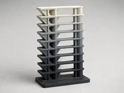
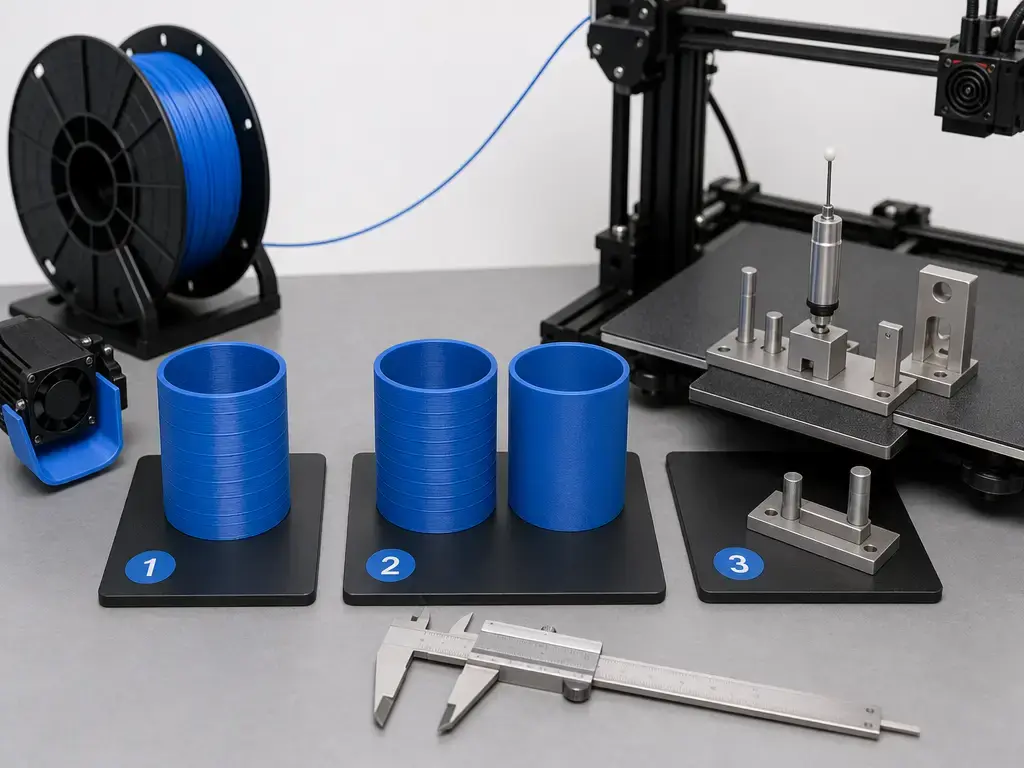
- Print a smooth-wall test part, such as a cylinder or tower, so the sidewall pattern is easy to read.
- Mark or measure the band spacing and decide whether it stays repeatable with height. [4] [22]
- Reprint at a different layer height and check whether the visible spacing changes with the print settings or stays tied to machine motion.
- Check slicer preview for seam location and any obvious wall-speed anomalies, because the perimeter must start and end somewhere and seam controls can move a vertical scar. [8]
- Identify the machine architecture before guessing at the cause: single Z, dual-Z, belt-synced dual-Z, independent dual-Z, bed slinger, CoreXY, cantilever Z, or another layout. If the machine has supported multi-Z alignment, a firmware tool such as Marlin G34 is one example of probe-based Z-stepper alignment. [12]
- Verify extrusion basics, including spool drag, diameter settings, and partial-clog symptoms. Wet filament can show poor surface quality, low layer adhesion, blobs, bubbling, and smoke during extrusion. [11]
- Check temperature stability and look for obvious cycling before touching motion hardware. Simplify3D uses about ±2 °C as a troubleshooting guideline for a stable extruder. [4]
- Change one variable and reprint.
Follow OEM guidance for manual axis movement. If no official procedure exists, do not force axes by hand; use controlled jog moves instead. Keep notes and photos under the same lighting, because the one-variable rule only works if the before/after comparison is actually comparable.
How to Fix Z Banding on a 3D Printer (Least Invasive First)
How to fix z banding on a 3d printer starts with a simple rule: document the baseline first. Take repeatable photos under the same raking light, print the same test object, and avoid changing three things at once.
The low-risk fixes come before replacement parts. Clean and lubricate motion parts according to the printer’s own maintenance guidance. Check whether the Z path is being side-loaded or over-constrained by misalignment rather than under-tightened. Reject blanket advice to “tighten everything,” because extra preload can create binding instead of solving it. On the extrusion side, check spool drag, confirm diameter and material settings, and deal with partial-clog symptoms before assuming the screw is bad. If a clog is suspected, a cold pull can be a useful maintenance step on supported machines, but Prusa’s widely cited PLA example at 270 °C and then 85 °C is specifically an MK-series procedure, not a universal temperature recipe. [13] Wet filament also remains a major lookalike because Prusa lists poor surface quality, blobs, bubbling, and smoke among the common symptoms of moisture-affected filament. [11]
Firmware compensation has a narrow role. Klipper’s pressure advance and Marlin’s Linear Advance target extrusion-pressure transients, not bent screws or misaligned Z motion. [5] [6] Klipper also notes typical pressure-advance values between 0.050 and 1.000 and says that no meaningful improvement up to 1.000 is a sign that pressure advance is probably the wrong lever. [5] Input shaping is for ringing caused by vibration after quick direction changes, not for true z banding. [7] Bed mesh is for first-layer compensation and cannot compensate for mechanical or electrical issues higher in the print. [10] Treat anti-backlash nuts as machine-specific parts, not default purchases, because they may add friction depending on the design and setup. Replace a lead screw, coupler, or other Z hardware only after the pattern has been reproduced, measured, and linked to motion periodicity.
Measuring Banding Instead of Guessing
Use the tool that matches the scale of the claim. ISO/ASTM 52902:2023, published in 2023-08 and listed at 40 pages, is useful here because it frames what to measure on AM benchmarking artifacts while explicitly not dictating one measurement method. [2]
- Macro photos — best for comparing pattern shape and repeat spacing before and after one change.
- Calipers — useful only for coarse diameter drift checks on simple geometry, not for local waviness amplitude claims.
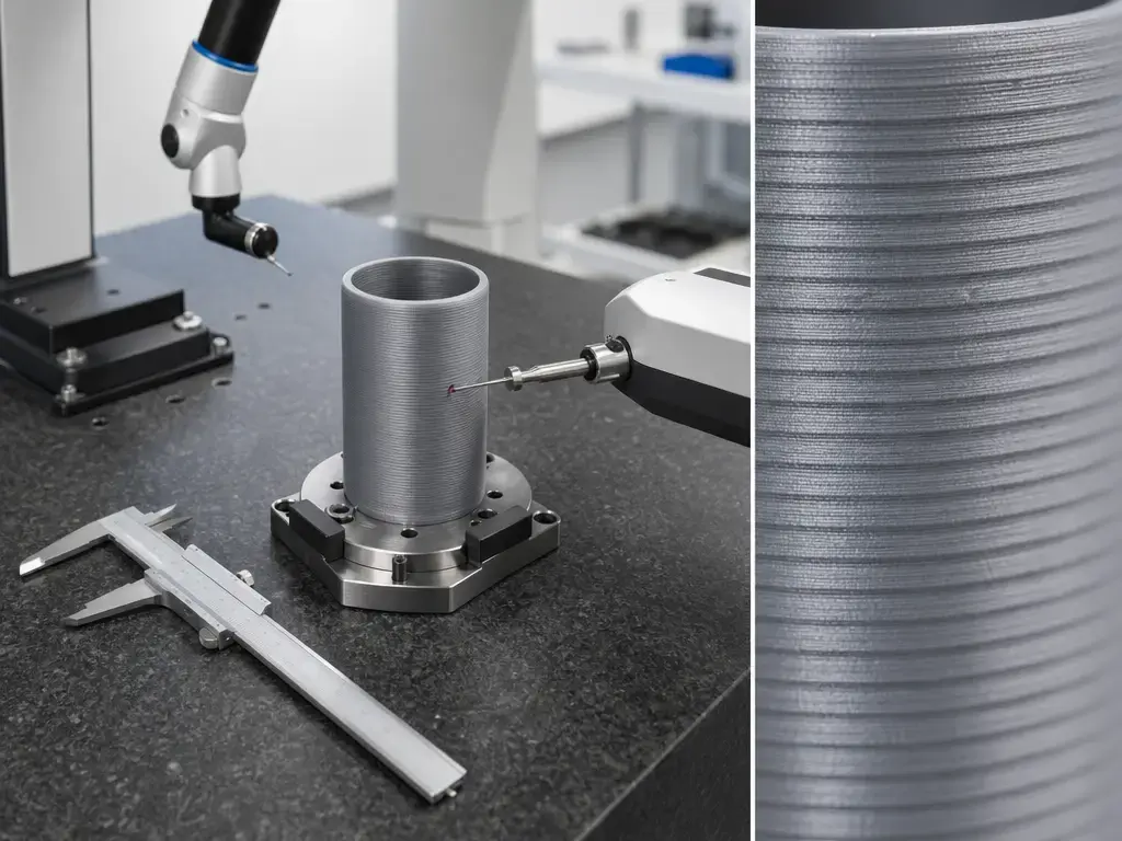
- Profilometer / roughness tools — better for local surface-height or roughness measurements in lab-style work.
- CMM — useful when the question is larger-scale geometry and coordinate comparison, not visual wall texture alone.
That warning matters because some artifacts are simply too small for hobby instruments. Prusa’s VFA article describes vertical micro-artifacts visible from about 10 µm, with the worst examples in that article around 40 µm peak-to-valley, and explicitly says that scale is too small to show up reliably on much metrology equipment. [15] So if you are tempted to declare a banding amplitude from caliper jaws on a glossy wall, stop. For a universal “acceptable z banding” threshold, no reliable figure found. [2]
Where Z Banding Matters Most
Z banding is often cosmetic on decorative parts, but it matters more on cylinders, enclosures, display pieces, post-processed show surfaces, and sliding fits where wall quality affects assembly, sanding, painting, or how cleanly a part looks under reflected light. The importance is contextual rather than universal: the same artifact that is tolerable on a shop jig may be unacceptable on a client-facing enclosure.
Limitations and Frequent Misdiagnoses
Normal layer stepping is not the same thing as z banding. Layer stepping is the expected staircase texture of a layered process, especially on sloped surfaces, while z banding is an abnormal repeating pattern on walls that otherwise should read as smooth. [1] Seam artifacts are another common false positive: Prusa’s documentation is clear that each perimeter loop must start and end somewhere, creating a vertical seam. [8] Ringing is different again, because Klipper defines it as echoing, ghosting, or rippling caused by mechanical vibration after quick direction changes. [7] Under-extrusion is recognizable by missing material in the layers, not by a clean height-repeatable ridge pattern. [14] Wet filament can also muddy the picture because Prusa lists poor surface quality, blobs, bubbling, smoke, and low layer adhesion as common moisture-related symptoms. [11]
First-layer tools sit in their own branch. Prusa’s Live Adjust Z is for fine-tuning nozzle distance on the first layer; too high hurts adhesion, and too close can stop filament from flowing out properly and risk a clog. [9] Klipper’s Bed Mesh likewise targets bed-surface irregularities for a better first layer and cannot compensate for mechanical or electrical issues. [10] If the defect runs up the whole wall, first-layer fixes are usually the wrong diagnostic path.
Research and Market Context (Keep It Short and Useful)
The standards boundary is useful but narrow. ISO/ASTM 52900:2021, Edition 2, was published in 2021-11, is listed at 28 pages, and was reviewed and confirmed in 2025; it provides general AM vocabulary rather than a consumer z banding definition. [1] ISO/ASTM 52902:2023, Edition 2, was published in 2023-08, is listed at 40 pages, and frames benchmarking artifacts and measurement targets without prescribing one specific measurement method. [2] NIST’s AM Bench page says the 2018 and 2022 rounds were completed, AM Bench 2025 is nearly completed, and planning for 2028 is underway. [21]
Firmware features also need to stay in their lane. Input shaping targets resonance and ringing. [7] Pressure advance and Linear Advance target extrusion-pressure transients. [5] [6] Bed mesh targets first-layer compensation. [10] Academic studies are useful as setup-dependent context, not recipes: a 2023 copper-filled PLA study used 10 mm × 10 mm × 20 mm specimens and reported that Z-direction dimensional error depended strongly on print speed and its interaction with layer height; a 2024 Taguchi study reported one flatness-optimal factor combination at 0.1 mm layer height, ABS, 30 mm/s, and a 0.4 mm nozzle; a 2025 ABS roughness study reported roughness approaching 4.24 µm under its stated conditions; and a PLA study first published online on January 22, 2025 and published in a February 2026 issue said 0.1 mm layer height most strongly affected Ra and Wa, while triangle infill produced a minimum width error of 0.3384%. [17] [18] [19] [20]
Key Takeaways: Diagnosing Z Banding Without Guesswork
Z banding is best treated as a pattern to test, not a label to guess. Check whether it repeats at a fixed height interval, separate it from seams and ringing, and use the least invasive fix that matches the evidence before replacing hardware.
FAQ
What is z banding in 3D printing?
Z banding is a visible wall artifact that usually appears as repeated horizontal lines, bands, or waves on vertical surfaces. The key qualifier is repeatability: not every line is z banding, because seams, ringing, wet-filament defects, and VFAs can produce very different marks that people describe with the same casual language. [3] [7] [8] [11] [15]
Z wobble vs z banding: what is the difference?
The useful distinction is that z banding is the symptom on the print, while z wobble is one possible cause category behind that symptom. In practice, people mix the terms, but the troubleshooting value comes from separating the visible pattern from the mechanism that might be creating it. [3]
What causes z banding on 3D prints?
Common causes include periodic Z-motion issues, constrained or misaligned motion paths, extrusion inconsistency, temperature cycling, and machine-dependent slicer visibility effects. Simplify3D’s examples are useful here because they show that side-wall lines can come from extrusion variation and thermal instability, not only from screws or couplers. [4]
How do I fix z banding on a 3D printer without replacing parts first?
Start with evidence, not parts. Print a simple wall test, measure whether the pattern repeats at a fixed height interval, compare seam placement in preview, check extrusion basics, and confirm temperature stability. Pressure Advance or Linear Advance tuning can help extrusion-pressure issues, but they do not repair a true Z-motion fault. [5] [6] [8]
Are vertical lines on a 3D print always z banding? (seam vs VFA vs banding)
No. A seam is a vertical start-stop line because each perimeter has to begin and end somewhere, while VFAs are microscopic vertical micro-lines that repeat at the same point in each layer. Z banding, by contrast, is usually discussed as repeating horizontal bands or waves on the wall. [3] [8] [15]
Expert: How can repeat distance point to a lead screw / coupler issue, and what should I measure first? (non-numeric unless printer spec is known)
Measure the vertical spacing between repeated bands first and ask whether it stays constant. If it does, compare that spacing with the Z drive’s repeat-distance logic, using lead rather than pitch alone. Thomson defines lead as the distance traveled in one screw revolution, and for multi-start screws that is not the same as pitch. If the printer’s screw specification is unknown, say no reliable figure found and keep testing non-numerically. [22]
Expert: When can pressure advance / linear advance changes improve wall artifacts — and when are they irrelevant?
They can help when the wall defect is caused by extrusion-pressure behavior, such as blobbing or over/under-fill around motion changes. Klipper’s Pressure Advance and Marlin’s Linear Advance both target that class of problem, not mechanical Z errors. If no meaningful improvement appears even up to Klipper’s 1.000 pressure-advance upper troubleshooting range, it is probably the wrong fix path. [5] [6]
Sources
- ISO/ASTM 52900:2021 Additive manufacturing — General principles — Fundamentals and vocabulary
- ISO/ASTM 52902:2023 Additive manufacturing — Test artifacts — Geometric capability assessment of additive manufacturing systems
- All3DP — Z-Banding/Z-Wobble: How to Fix It
- Simplify3D — Lines on the Side of Print
- Klipper — Pressure Advance
- Marlin — Linear Advance
- Klipper — Resonance Compensation
- Prusa Knowledge Base — Seam position
- Prusa Knowledge Base — Live Adjust Z
- Klipper — Bed Mesh
- Prusa Knowledge Base — Drying filament
- Marlin — G34 Z Steppers Auto-Alignment
- Prusa Knowledge Base — Cold pull (MK-series)
- Prusa Knowledge Base — Under-extrusion
- Prusa Blog — Consistent surface finish and nerfing VFAs
- Tom’s Hardware — How to Fix Z-Banding in 3D Printing
- MDPI Metals (2023) — copper-filled PLA FFF dimensional accuracy
- MDPI Metrology (2024) — dimensional deviations / Taguchi factors
- ScienceDirect / Next Materials (Apr 2025) — ABS roughness trend
- SAGE / IMechE journal page (online 2025; issue 2026) — PLA parameter sensitivity
- NIST — AM Bench
- Thomson Linear — Lead Screws: Lead vs Pitch