
Summary
Metal vs plastic 3D printing is a practical comparison between additive manufacturing routes that make parts from metals and those that make parts from polymers. Both start from a digital model and build a physical object by adding material rather than cutting it away. ISO/ASTM 52900 defines additive manufacturing as building physical three-dimensional geometries by successive addition of material, and NIST describes the same digital-to-part idea as fabricating products layer by layer. [01] [02] The difference is not just “strong metal” versus “cheap plastic.” It is a choice among process families, materials, machine constraints, finishing steps, inspection needs, and certification expectations. [03]
A useful comparison starts with the part’s job: mechanical load, service temperature, chemical exposure, wear, electrical or thermal behavior, expected lifetime, tolerance chain, surface finish, support removal, heat treatment or curing, machining, cleaning, inspection, qualification, and budget. NIST’s additive manufacturing taxonomy includes powder bed fusion, directed energy deposition, material extrusion, vat photopolymerization, and binder jetting, among other routes. [03] For prototypes, jigs, housings, and ergonomic checks, polymer routes are often simpler. For load-bearing brackets, tooling inserts, heat-exposed parts, and high-value repairs, metal routes may justify the higher process and verification burden. The best answer is rarely a binary printer showdown; it is a requirements match.
What Readers Usually Mean by This Comparison
Most confusion in metal vs plastic 3D printing comes from comparing unlike systems: industrial metal powder bed fusion against a desktop polymer material extrusion printer, or a resin prototype against a sintered steel production part. Standards vocabulary helps separate material class from process family, and NIST lists multiple additive manufacturing families rather than one generic “3D printing” method. [01] [03]
Terminology box. The terms below follow ISO/ASTM terminology and common additive manufacturing usage. [01] [03]
- Material class: metal, polymer, ceramic, composite, or hybrid.
- Process family: method category, such as powder bed fusion, directed energy deposition, material extrusion, vat photopolymerization, or binder jetting.
- Feedstock: the input material, such as filament, resin, powder, wire, paste, or bound-metal rod.
- Green part: a printed part that still contains binder before final thermal densification.
- Brown part: an intermediate part state in a debind-and-sinter workflow before final densification.
- Sintered part: the densified part after heat treatment fuses particles.
- Resolution: smallest feature the system can represent.
- Accuracy: closeness to nominal geometry.
- Repeatability: consistency across repeated builds.
- Layer thickness: height of each deposited or solidified layer.
- Strength: resistance to failure under load.
- Stiffness: resistance to elastic deflection.
- Toughness: resistance to crack growth or impact failure.
- Heat resistance: ability to retain useful properties at service temperature.
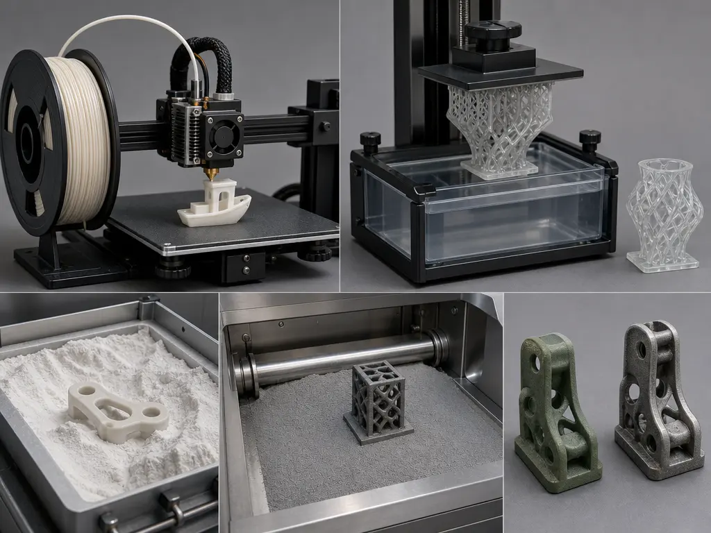
In this article, decorative metal-filled filament does not count as structural metal additive manufacturing. A bronze- or steel-filled polymer filament may polish or weigh more like metal, but the load path is still mostly polymer unless a validated debinding and sintering workflow produces a metallic part. Bound-metal systems intentionally print a green part, then remove binder and sinter the part to reach the final metal condition. Desktop Metal describes this route as extrusion of bound metal rods followed by furnace processing that densifies parts up to 98%; that is a manufacturer claim for that workflow. [19] [20]
True metal routes produce metal parts by melting, solidifying, or sintering metallic feedstock. That distinction controls density, shrinkage, supports, heat treatment, inspection, and dimensional compensation. In binder jetting, for example, parts shrink during sintering, and Desktop Metal’s design guide says shrinkage may be as high as 20%, depending on material. [21] The rest of this article compares the decision variables behind those outcomes, not just the label on the printer.
Comparison Framework: What Actually Changes from Plastic to Metal
Before making performance claims, compare the variables that actually change: feedstock, process family, machine class, build envelope, layer-height range, dimensional behavior, post-processing burden, safety controls, throughput, workflow time, end-use suitability, and cost drivers. NIST groups additive manufacturing technologies into distinct process families, so a polymer vat photopolymerization part, a thermoplastic material extrusion part, a laser powder bed fusion metal part, and a binder-jetted metal part should not be treated as variants of one process. [03] Feedstock form—powder, wire, filament, pellet, resin, or bound-metal media—affects handling, consolidation, supports, surface finish, and the inspection plan.
Layer height is often quoted first, but it is not the same as accuracy, repeatability, or tolerance after finishing. Dimensional behavior depends on the route: melting, curing, extrusion, binding, debinding, sintering, machining, or heat treatment can all shift final geometry. Mechanical and thermal comparisons also need a named material, build orientation, post-processing state, and test condition. ISO/ASTM 52920 frames qualification as a quality-assurance issue across additive manufacturing technologies and production sites, not as a single printer setting. [10]
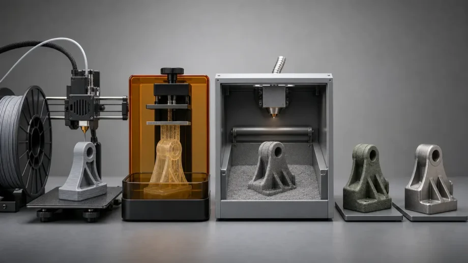
Metal vs Plastic 3D Printing: Process Families
Polymer routes
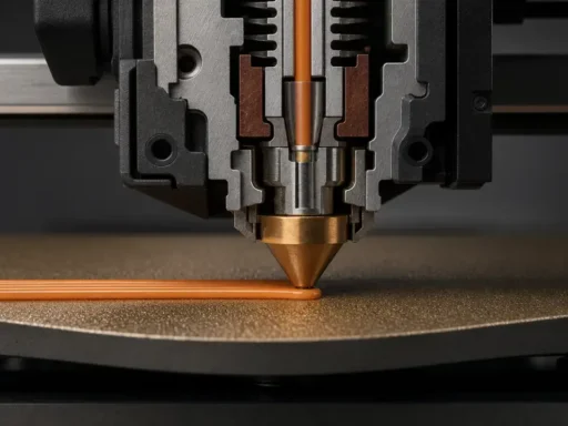
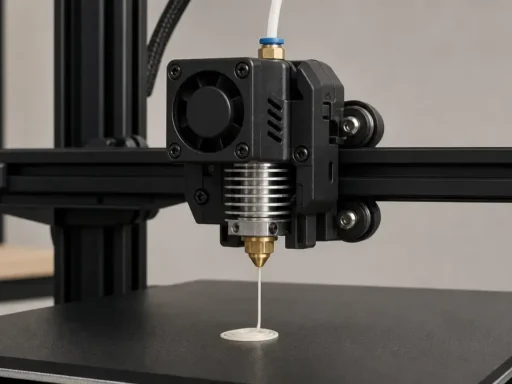
NIST’s plain-language framing is that digital designs are used to fabricate products layer by layer, but the way each layer becomes solid differs sharply by process family. [02] [03] For plastic 3D printing, the most common routes are polymer material extrusion, vat photopolymerization, and polymer powder bed fusion, including selective laser sintering, or SLS. Desktop polymer extrusion gives a useful scale reference: the Original Prusa MK4S lists a 250 × 210 × 220 mm build volume and a 0.05–0.30 mm layer-height range. [16] Resin systems cure liquid photopolymer layer by layer, while polymer SLS fuses powder in a bed where unused powder supports the part. EOS describes SLS as suitable for prototypes and end-use polymer parts, including robotic parts, gripping systems, plastic housings, spare parts, and medical-response production examples. [22]
Metal routes
For metal 3D printing, common industrial routes include metal powder bed fusion, with laser and electron-beam variants, plus binder jetting followed by sintering and bound-metal deposition workflows. NIST lists powder bed fusion, directed energy deposition, material extrusion, vat photopolymerization, and binder jetting as separate AM technology groups, so the metal side is already a family of different processes before alloy choice enters the discussion. [03] In metal powder bed fusion, the part is metallic after melting and solidification, but it commonly still needs depowdering, support removal, stress relief or heat treatment, machining, and inspection. As an industrial example, the EOS M 290 lists a 250 × 250 × 325 mm build volume, scan speed up to 7.0 m/s, and an approximately 100 µm focus diameter. Those are machine metrics, not direct proxies for finished-part throughput, tolerance, or strength. [13]
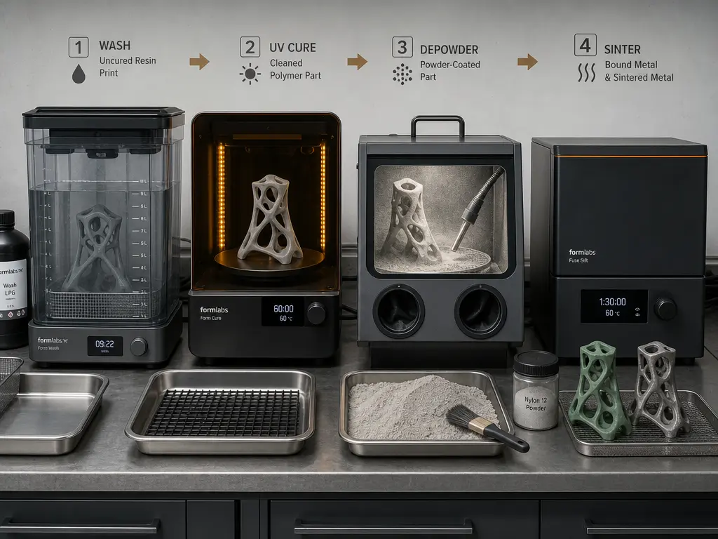
Binder jetting and bound-metal deposition differ because the printed state is not yet the final dense metal state. In Desktop Metal’s bound-metal route, a green part is shaped by extruding bound metal rods, then goes through thermal processing that removes binder and fuses metal particles, with the company describing densities up to 98% for its system. [19] Desktop Metal’s sintering explanation also uses the term brown part for an intermediate powder-and-binder state in the furnace cycle before full densification. [20] Binder-jetted metal parts likewise require sintering, and Desktop Metal’s binder-jet guide says shrinkage during sintering may be as high as 20%, depending on material. [21] That is why melted metal PBF parts, binder-jetted parts, and bound-metal parts should not be treated as if they leave the machine in the same condition.
Table 1 — Process-family comparison. [03] [19] [20] [21] [22]
| Process family | Typical feedstock | Consolidation route | Typical post-processing |
|---|---|---|---|
| Polymer material extrusion | Thermoplastic filament or pellet | Melt and resolidify extruded bead | Support removal, trimming, optional finishing |
| Vat photopolymerization | Liquid photopolymer resin | Light-triggered curing | Washing, post-curing, support removal |
| Polymer PBF / SLS | Polymer powder | Laser sintering within powder bed | Cooling, depowdering, blasting or dyeing |
| Metal PBF / LPBF / EBM | Metal powder | Laser or electron-beam melting | Depowdering, stress relief, support removal, machining |
| Metal binder jetting | Metal powder plus deposited binder | Binder deposition, then sintering | Curing, depowdering, sintering, support management, machining if required |
| Bound-metal deposition / BPE / metal FFF | Bound metal-polymer rod or filament | Extrusion of bound feedstock, then binder removal and sintering | Thermal processing, shrinkage compensation, finishing |
Performance Metrics That Matter
“Stronger” is too vague to describe print strength or part durability. Strength is resistance to failure under load, stiffness is resistance to elastic deflection, and toughness is resistance to crack growth or impact-type failure. A material can be stiff but brittle, tough but flexible, or strong only in a favorable build direction. For polymers, ASTM D638 is a common tensile-test anchor, but it explicitly notes that results vary with specimen preparation, test speed, and environment. [05] For metals, tensile testing is commonly anchored to standards such as ASTM E8/E8M, while specific additive-manufacturing datasheets may use other named test methods. [07]
Example values help only when the material and condition are named. EOS reports for Aluminium AlSi10Mg Light, on as-manufactured machined samples tested to ISO 6892-1 B10, vertical Rp0.2 of 230 MPa, Rm of 460 MPa, and elongation A of 6.3%, with horizontal values of Rp0.2 at 270 MPa, Rm at 450 MPa, and A at 10.2%. [15] Those are not category-wide metal claims; they are material-, orientation-, and condition-specific figures. Formlabs reports Tough 2000 Resin V2, from parts printed on a Form 4 at 100 µm and post-cured at 70 °C for 12 minutes, with post-cured ultimate tensile strength of 40.4 MPa and elongation at break of 79% under ASTM D638-14. [17] [18]
Heat resistance needs the same caution. The same Formlabs TDS lists Tough 2000 Resin V2 at an HDT of 70 °C at 0.45 MPa, measured by ASTM D648-16, but ASTM D648 warns that HDT data should not be used to predict elevated-temperature behavior except under similar conditions and is not intended for design or endurance prediction. [18] [06] In other words, HDT is a screening metric under a defined flexural load, not a universal safe operating temperature. A polymer HDT value should therefore not be compared directly with unspecified “metal heat resistance” as if both numbers meant the same thing.
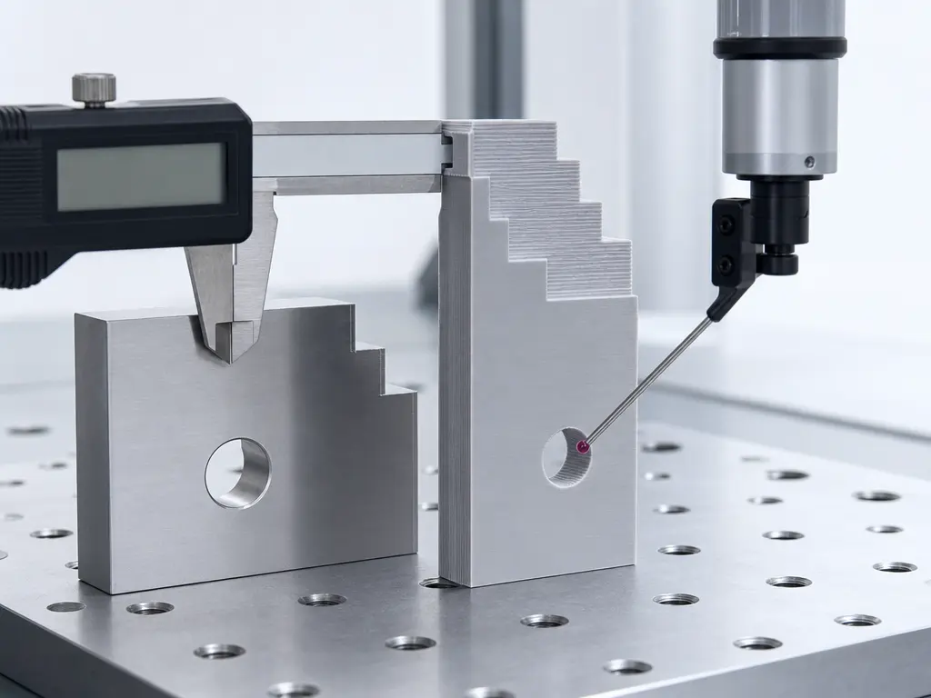
Dimensional metrics are just as easy to mix up. Resolution describes the smallest addressable or representable feature, layer thickness is only the height of each layer, accuracy is closeness to nominal geometry, and repeatability is how consistently the process returns to the same result. The Prusa MK4S layer-height range of 0.05–0.30 mm is therefore not an accuracy claim. [16] Likewise, EOS M 290 values such as 250 × 250 × 325 mm build volume, scan speed up to 7.0 m/s, and approximately 100 µm focus diameter describe machine capability and beam motion, not finished-part tolerance or strength. [13] A second metal example makes the distinction clearer: 3D Systems lists for the DMP Flex 350 a minimum 5 µm layer, typical 30/60/90 µm layers, repeatability of 60 µm at 3σ on x, y, and z, and typical accuracy of ±0.1–0.2% with a ±100 µm minimum. Those are different published metrics and should not be treated as interchangeable. [14]
Surface finish and anisotropy add another layer of caution. A part described as as-built, post-processed, or machined-final is not in the same dimensional or surface condition, even when it came from the same machine. Surface finish varies by orientation, support strategy, powder or resin behavior, and finishing route. For an audited, cross-process roughness number covering the examples above, no reliable figure found. Anisotropy also remains a central caveat: layerwise construction can make vertical, horizontal, and off-axis properties differ, especially before final post-processing. [15] [18]
Metrics buyers often confuse
- Layer thickness vs dimensional accuracy: thinner layers can improve stair-stepping, but calibration, shrinkage, curing, heat, and finishing still control final dimensions.
- Resolution vs minimum feature size: a small voxel, nozzle path, or beam spot does not guarantee a durable wall, pin, thread, or hole.
- Accuracy vs repeatability: a printer can repeat the same offset reliably and still be inaccurate without compensation. [14]
- As-built vs machined-final condition: compare parts in the same condition label, because curing, sintering, heat treatment, support removal, and machining can change geometry and properties. [15] [18]
- Strength vs stiffness vs toughness: a high tensile number does not automatically mean a part resists bending, fatigue, impact, or crack growth.
- Heat resistance vs HDT: HDT is measured under a defined flexural load and is not an endurance limit. [06]
Workflow, Post-Processing, and Safety
Workflow is where the metal-versus-polymer split often becomes most visible. In polymer material extrusion, the sequence is usually model preparation, slicing, printing, support removal, and light finishing; the main constraints are support access, bed adhesion, and thermal warping. Resin vat photopolymerization adds liquid resin handling, washing, post-curing, and careful disposal of contaminated consumables. Polymer powder bed fusion avoids many support structures because unsintered powder supports the part, but it still requires cooling time, depowdering, powder management, and surface finishing. EOS’s SLS description and Formlabs’ end-use guidance both frame polymer AM as a workflow rather than a single print step. [22] [23]
Metal workflows generally add more controlled downstream operations. Metal powder bed fusion commonly includes powder handling, printing, depowdering, support removal, stress relief or heat treatment, and optional machining of critical faces, holes, or datums. Bound-metal systems form a green part from bound feedstock and then rely on furnace processing to remove binder and densify the metal. Desktop Metal describes that route as extrusion of bound rods followed by sintering that can densify parts up to 98%, which remains a manufacturer claim for that system. [19] Desktop Metal’s sintering guidance also uses the brown-part label for an intermediate furnace state before full densification. [20] Metal binder jetting follows a print-depowder-sinter path, with dimensional compensation for shrinkage; Desktop Metal’s binder-jet design guide says shrinkage may be as high as 20%, depending on material. [21]
Safety also separates the workflows. Desktop material extrusion is not risk-free: ISO/ASTM 52933 specifies a test method for measuring hazardous substances emitted during operation of material-extrusion AM machines in non-industrial places and includes suggestions for reducing them. [09] Resin printing adds skin-contact and ventilation concerns. Metallic powders bring combustible-dust, inhalation, contamination, static, housekeeping, and waste-handling issues. ISO/ASTM 52931 addresses risk assessment and prevention or protection measures for additive manufacturing with metallic powders across all subprocesses, including waste management. [08] Debinding and sintering add furnaces, atmosphere control, off-gassing, and part-handling requirements. For generalized hard cost claims such as “metal is always X times more expensive” or “plastic is always faster,” no reliable figure found.
Main workflow and cost drivers
- Machine cost: printer, furnace, washer, curing unit, powder station, or machining equipment.
- Feedstock cost: filament, resin, polymer powder, metal powder, bound rods, binders, and consumables.
- Labor: setup, support strategy, depowdering, washing, inspection, fixturing, and rework.
- Post-processing: curing, heat treatment, binder removal, sintering, support removal, surface finishing, and machining.
- Yield / scrap: failed builds, cracked green or brown parts, warped polymers, powder contamination, and out-of-tolerance parts.
- QA / inspection: dimensional checks, material traceability, test coupons, documentation, and qualification evidence.
- Facility burden: ventilation, powder containment, fire protection, waste controls, compressed gas, furnaces, and training.
- Total workflow time: printing time plus cooling, cleaning, curing, thermal processing, machining, and inspection.
Applications and Material Applications
Plastic 3D printing commonly fits prototypes, ergonomic models, jigs, fixtures, housings, ducts, spare parts, and selected end-use runs where polymer properties are sufficient. EOS lists SLS examples including robotic parts, gripping systems, plastic housings, spare parts, and mass-produced medical-response parts, which places the technology beyond visual models. [22] Formlabs also documents end-use part applications across manufacturing workflows. [23] In material applications, the key point is that polymer use cases should stay tied to route and material rather than to a generic claim that plastics now equal metals.
Metal 3D printing is more often considered when the part must carry higher loads, tolerate higher temperatures, consolidate complex geometry, or justify expensive inspection. Common targets include brackets, tooling inserts, heat-loaded components, medical and dental parts, and aerospace or energy hardware. A metal example still needs condition labels: EOS reports Aluminium AlSi10Mg Light values for as-manufactured machined samples, with vertical Rp0.2 of 230 MPa, Rm of 460 MPa, and A of 6.3%, and horizontal Rp0.2 of 270 MPa, Rm of 450 MPa, and A of 10.2%. [15]
Substitution is selective, not universal. A polymer duct may replace sheet metal if temperature, stiffness, flammability, and fastener loads are acceptable. A metal printed insert may replace machined tooling if conformal cooling or part consolidation offsets the extra qualification burden. Sintering-based metal routes need extra caution in direct substitutions: bound-metal and binder-jetted parts reach final properties only after thermal processing, so route context matters as much as the alloy name. [19] [20] Binder jetting also adds dimensional risk because shrinkage during sintering may be as high as 20%, depending on material, which complicates one-for-one replacement of a machined or molded part. [21]
Qualification, Inspection, and Cost Drivers
Qualification is not a generic “industrial-grade” label. It is a documented match between a process, material, machine, site, operator practice, inspection plan, and end-use requirement. ISO/ASTM 52920 defines quality-assurance measures along the manufacturing process for industrial additive manufacturing processes and production sites, across AM technologies rather than for a single printer category. [10] That matters for both polymers and metals, but the burden often rises for metal parts because powder handling, thermal history, residual stress, porosity, heat treatment, machining, and traceability can all affect the final part. NIST’s metals work is built around metrology tools, measurement standards, and process-structure-property-performance relationships, which underscores the same point. [04]
Metal additive manufacturing adds sector-specific standards when the application is critical. ISO/ASTM 52904 covers operation and production control of metal powder bed fusion processes for critical applications, rather than treating a successful print as sufficient evidence. [11] ISO/ASTM 52941 specifies qualification and re-qualification tests for laser metal powder bed fusion machines for aerospace and says it can also be used for periodic inspections or checks after maintenance and repair. [12] These documents do not create one universal tolerance or inspection recipe; they show that acceptance tests, production control, and requalification depend on the sector and process.
Cost is therefore hard to universalize. Metal routes are often more burdensome because of machine cost, powder controls, thermal processing, machining, inspection, documentation, and facility requirements, including the environment, health, and safety controls addressed in ISO/ASTM 52931. [08] Fatigue and fracture deserve special caution as well: a part that meets a static tensile target may still need application-specific evidence if it will see cyclic load, defects, or safety-critical service. NIST explicitly notes that metal AM is not yet used in fatigue- and fracture-critical applications despite industrial need. [04] For buying decisions, the real comparison is qualified part cost and risk, not build price alone.
Choosing by Constraint, Not by Hype
The practical way to choose is to rank constraints before choosing a material class. Start with load, service temperature, tolerance chain, surface and finish needs, geometry complexity, certification burden, production volume, and budget. Polymer SLS can support prototypes and end-use parts, while resin and extrusion routes may be better for fast iteration, fit checks, or ergonomic trials. [22] A route-specific polymer example is Tough 2000 Resin V2, where the reported tensile and HDT values apply to that resin, print setup, and post-cure condition, not to all polymers. [17] [18] Metal becomes more attractive when the part must tolerate higher structural or thermal demand, when assembly reduction has high value, or when post-machining and inspection are acceptable. Even then, compare condition labels: EOS AlSi10Mg values differ by orientation, and one LPBF system’s published typical accuracy of ±0.1–0.2% with a ±100 µm minimum is still only a vendor-typical claim for a specific machine and stated conditions. [15] [14]
Process burden can outweigh material appeal. Metal powder workflows bring environment, health, and safety requirements that must be planned, not improvised. [08] Bound-metal systems move from a printed green part to a sintered metal state, so the final part is not defined by the print step alone. [19] Binder jetting adds another caution: shrinkage during sintering may be as high as 20%, depending on material, which affects tolerances, fixtures, and scrap risk. [21] In metal vs plastic 3D printing, neither class is universally better; the right choice is the route that best matches the qualified part requirement.
Table 2 — Constraint-based decision matrix. [08] [15] [18] [19] [21] [22]
| Constraint | Usually points toward polymer AM | Usually points toward metal AM | Caveat |
|---|---|---|---|
| Fast, low-cost iteration | Concept models, fit checks, fixtures | Only if metal behavior must be tested | Compare full workflow time |
| Higher service temperature | High-temperature polymers in limited cases | Heat-loaded parts | Verify actual service condition |
| Higher structural load | Light-duty or compliant parts | Load-bearing brackets or inserts | Test orientation and defects |
| Office-friendly workflow | Many extrusion workflows | Rarely powder metal | Emissions and resin handling still matter |
| Tighter qualification burden | Noncritical aids or prototypes | Critical certified hardware | Qualification can dominate cost |
| Small-batch end-use production | Housings, ducts, spare parts | High-value functional parts | Volume changes the economics |
| Post-machining allowed | Usually less central | Often useful for datums and fits | Adds cost and lead time |
| Complex geometry with lower assembly count | Ducts, lattices, custom housings | Internal channels, consolidated metal parts | Complexity must justify inspection |
Common Misreads and Comparison Traps
The first trap is the universal statement: “metal is always stronger” or “plastic is only for prototypes.” Some polymers are useful in end-use parts, and some printed metal parts are inappropriate without heat treatment, machining, inspection, or qualification. Strength also changes with build orientation, defects, post-processing, and test method, so a condition-free number is not a design value. [15] [22]
The second trap is metric substitution. ASTM D638 tensile results for plastics vary with specimen preparation, test speed, and environment, so a polymer datasheet value needs context. [05] Heat deflection temperature is also often misread as a service-temperature rating; ASTM D648 is a defined flexural-load test, not a universal endurance or design limit. [06]
The third trap is treating machine specs as part specs. A published 5 µm minimum layer, 60 µm repeatability, and ±0.1–0.2% typical accuracy with a ±100 µm minimum are distinct metrics, not interchangeable guarantees. [14] The cleanup is simple: compare the same process family, named material, build orientation, post-processing condition, test standard, and inspection method before drawing conclusions.
Standards and Test Methods to Read Before Comparing Datasheets
Standards-based reading matters because datasheets often place one clean number in a messy testing context. For plastics, ASTM D638 is designed to produce tensile-property data for control and specification, but the result is tied to specimen preparation, test speed, and environment. [05] That makes it useful for comparison when the test basis is shared, not a universal prediction of every printed geometry.
For heat data, ASTM D648 covers deflection temperature of plastics under flexural load. Its key limitation is interpretive: HDT should not be treated as a design value or endurance prediction. [06] It is better read as a screening point under a defined load.
For metals, ASTM E8/E8M covers room-temperature tension testing of metallic materials and reports properties such as yield strength, tensile strength, elongation, and reduction of area. [07] When comparing metal and polymer results, check whether the specimen was as-built, heat-treated, machined, cured, aged, dry, conditioned, or tested in a particular build orientation.
FAQ
What is the difference between metal and plastic 3D printing?
Both are additive manufacturing: physical 3D geometry is built by adding material, and NIST describes fabrication from digital designs layer by layer. [01] [02] The difference is the material class and process route. Plastics commonly use extrusion, vat photopolymerization, or polymer powder bed fusion; metals commonly use metal powder bed fusion, binder jetting, or sintering-based bound-metal routes. [03]
Which is better, metal or plastic 3D printing?
Neither is better in general. Metal may fit higher loads, heat, and regulated hardware, but it often brings powder safety, qualification, inspection, and process-control burdens. [08] [10] [11] [12] Plastic may fit prototypes, housings, fixtures, and selected end-use parts. Compare named materials and conditions, such as a specific AlSi10Mg dataset or a specific tough resin dataset, rather than comparing categories in the abstract. [15] [18]
Does metal-filled filament count as metal 3D printing?
Usually no. Decorative metal-filled filament is still mostly a polymer part unless a validated debinding and sintering workflow turns it into a real metal part. In true bound-metal systems, the printed green part contains binder, thermal processing removes binder, and sintering produces the final metal state. [19] [20] Binder-jet and bound-metal routes also need shrinkage management; Desktop Metal says binder-jet shrinkage during sintering may be as high as 20%, depending on material. [21]
Is plastic 3D printing only for prototypes?
No. Prototyping is common, but polymer printing also supports jigs, fixtures, housings, ducts, spare parts, and selected end-use production. EOS describes SLS uses that include robotic parts, gripping systems, plastic housings, spare parts, and medical-response production examples. [22] Formlabs also documents end-use part workflows for resin and SLS systems. [23]
Why doesn’t layer height equal accuracy in 3D printing?
Layer height describes only the vertical increment of each layer. Accuracy and repeatability are separate metrics. A desktop extrusion printer may list 0.05–0.30 mm layers, while a metal system can separately publish focus diameter, repeatability, and vendor-typical accuracy. [16] [13] [14] Smaller layers can improve stair-stepping, but they do not guarantee final dimensions.
Expert-level: How should I compare LPBF tolerances with binder-jet or bound-metal shrinkage allowances?
Start with the stated machine condition and inspection method for LPBF, and do not compare a vendor-typical accuracy figure directly to sintering shrinkage as if they were the same kind of number. Binder-jet and bound-metal parts change dimension during thermal processing, so shrinkage compensation is part of the process definition. Desktop Metal says binder-jet shrinkage may be as high as 20%, depending on material. [14] [19] [20] [21]
Expert-level: Which test standards matter when comparing tensile and heat-resistance data across printed metals and plastics?
For plastics, ASTM D638 anchors tensile-property testing, while ASTM D648 covers HDT under flexural load and should not be read as a universal service-temperature rating. [05] [06] For metals, ASTM E8/E8M covers room-temperature tension testing and reports yield strength, tensile strength, elongation, and reduction of area. [07] Always check specimen condition, orientation, and post-processing.
Sources
- ISO/ASTM 52900-21 — Additive manufacturing — General principles — Fundamentals and vocabulary. Standard, 2021. https://store.astm.org/f3177-21.html
- NIST — Additive manufacturing. Official documentation, current. https://www.nist.gov/additive-manufacturing
- NIST — Additive Manufacturing Technologies. Official documentation, current. https://www.nist.gov/additive-manufacturing/research-areas/technologies
- NIST — Additive Manufacturing of Metals. Official documentation, updated 2025. https://www.nist.gov/additive-manufacturing/research-areas/materials/metals
- ASTM D638-22 — Standard Test Method for Tensile Properties of Plastics. Standard, 2022. https://store.astm.org/standards/d638
- ASTM D648-18 — Standard Test Method for Deflection Temperature of Plastics Under Flexural Load in the Edgewise Position. Standard, 2018. https://store.astm.org/d0648-18.html
- ASTM E8/E8M-21 — Standard Test Methods for Tension Testing of Metallic Materials. Standard, 2021. https://store.astm.org/e0008_e0008m-21.html
- ISO/ASTM 52931-23 — Additive manufacturing of metals — Environment, health and safety — General principles for use of metallic materials. Standard, 2023. https://store.astm.org/f3546-23.html
- ISO/ASTM 52933-24 — Additive manufacturing — Environment, health and safety — Test method for the hazardous substances emitted from material extrusion type 3D printers in the non-industrial places. Standard, 2024. https://store.astm.org/f3655-24.html
- ISO/ASTM 52920-23 — Additive manufacturing — Qualification principles — Requirements for industrial additive manufacturing processes and production sites. Standard, 2023. https://store.astm.org/f3501-23.html
- ISO/ASTM 52904-24 — Additive manufacturing of metals — Process characteristics and performance — Metal powder bed fusion process to meet critical applications. Standard, 2024. https://store.astm.org/f3303-24.html
- ISO/ASTM 52941-20 — Additive manufacturing — System performance and reliability — Acceptance tests for laser metal powder-bed fusion machines for metallic materials for aerospace application. Standard, 2020. https://store.astm.org/f3472-20.html
- EOS M 290 system data sheet. Manufacturer, current. https://www.eos.info/metal-solutions/metal-printers/data-sheets/sds-eos-m-290
- 3D Systems DMP Flex 350 product page. Manufacturer, current. https://www.3dsystems.com/3d-printers/dmp-flex-350
- EOS Aluminium AlSi10Mg Light material datasheet. Manufacturer datasheet, 2025. https://www.eos.info/var/assets/05-datasheet-images/Assets_MDS_Metal/EOS_Aluminium_AlSi10Mg/Material_Datasheet_EOS_Aluminium_AlSi10Mg_EN.pdf?v=5
- Original Prusa MK4S product page. Manufacturer, current. https://www.prusa3d.com/product/original-prusa-mk4s-3d-printer/
- Formlabs Tough 2000 Resin V2 product page. Manufacturer, current. https://formlabs.com/store/materials/tough-2000-resin/
- Formlabs Tough 2000 Resin V2 TDS. Manufacturer technical data sheet, 2025. https://formlabs-media.formlabs.com/datasheets/251013-MS-TDS-Tough_2000_V2.pdf
- Desktop Metal Studio System page. Manufacturer, current. https://www.desktopmetal.com/products/studio/fleet/
- Desktop Metal — Thermal Debinding and Sintering 101. Manufacturer documentation, current. https://www.desktopmetal.com/resources/sintering-101
- Desktop Metal Binder Jet Design Guide. Manufacturer guide, 2022. https://www.desktopmetal.com/uploads/81-00239_Rev01_EN_Binder-Jet-Design-Guide.pdf
- EOS — Selective Laser Sintering (SLS). Official manufacturer documentation, current. https://www.eos.info/about-us/what-we-do/sls
- Formlabs — End-Use Parts. Official manufacturer documentation, current. https://formlabs.com/applications/end-use-parts/