
Summary (mandatory)
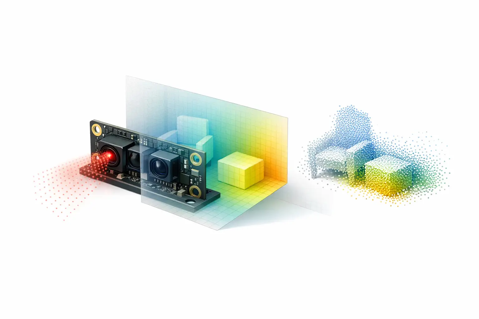
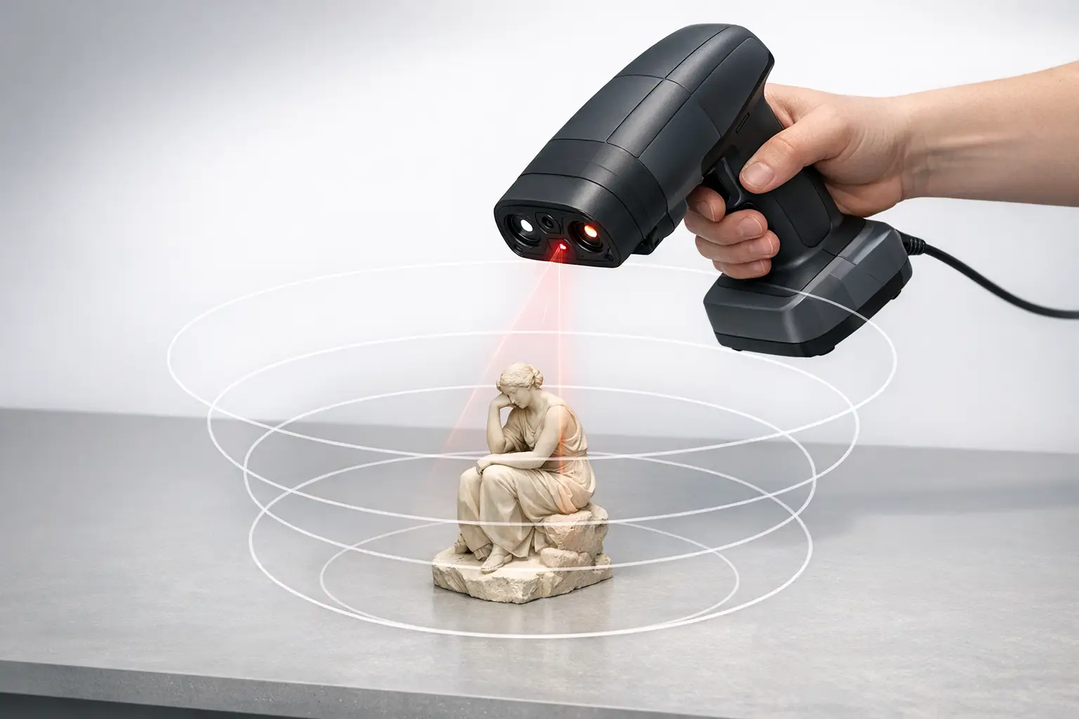
An IR 3D scanner (infrared 3D scanner) is a near-infrared (NIR) depth camera that illuminates a scene with non-visible light and estimates distance per pixel to form a depth map that can be converted into a point cloud. Common modalities include active stereo with an infrared projector, infrared structured light, and indirect time-of-flight (iToF) sensors. [1]
Because the scanner supplies its own illumination, infrared scan workflows can support low-light scanning; Apple states Face ID is designed to work “even in total darkness.” [9] However, ambient IR / sunlight interference can reduce usable depth outdoors, despite NIR emitters such as an 850 nm ± 10 nm projector specified for Intel RealSense D400-series devices. [1]
Definition and Scope (NIR vs thermal IR)
In 3D scanning, “infrared” typically refers to NIR illumination and imaging used for geometric ranging, not thermal infrared imaging used for temperature contrast. An “infrared scan” in this context is the acquisition of depth using an IR-sensitive imager and non-visible illumination, producing a depth map that may be fused into a point cloud or mesh; it does not imply any measurement of heat. Many commodity depth cameras implement this by combining stereo IR imagers with an infrared projector that projects a non-visible IR pattern to create artificial texture on otherwise feature-poor surfaces, with the projector sometimes described as optional depending on operating mode and lighting. [1] This scope includes small embedded modules (for example, Intel RealSense D400-series depth cameras) and accessory sensors (for example, the Structure Sensor (Mark II)) that publish NIR-depth specifications such as depth resolution, field of view (FOV), and recommended range. [1][6]
Historical Background (mandatory)
Infrared depth sensing reached broad developer adoption through game and human-interface research that prioritized real-time full-scene depth over metrology-grade accuracy. A prominent early lineage is Microsoft’s “Project Natal,” which later became Kinect, and relied on NIR depth sensing to support interactive tracking in indoor environments where visible-light cues alone were unreliable. Academic comparisons of Kinect-family depth cameras commonly frame this period as the transition of structured-light and time-of-flight depth from specialized labs into widely available consumer hardware and research platforms. [11]
In 2010, PrimeSense publicly announced it had been selected by Microsoft for Project Natal, reflecting the then-novel commercialization of NIR depth sensing for mass-market devices and developer ecosystems. [13] The subsequent availability of commodity depth cameras encouraged software stacks for real-time reconstruction, human pose estimation, and robotics perception, and it also established a recurring set of performance descriptors (range limits, FOV, and depth noise behavior under different materials and lighting) that remain central to how an IR 3D scanner is specified and evaluated. [11]
A later inflection point was the transition from dedicated, first-party depth kits toward partner hardware offerings. Microsoft announced it would end production of the Azure Kinect Developer Kit on Aug 17, 2023, and stated that the technology would transfer to a partner ecosystem. [2] In practice, this shifted many developers from treating a single reference device as a stable baseline toward designing around modality-level expectations (for example, iToF behavior under multipath interference (MPI) and ambient illumination) and around cross-vendor depth data products such as depth maps and point clouds rather than device-specific pipelines. [2]
Core Principles of Infrared 3D Scanning
Most infrared 3D scanners are “active” sensors: they emit NIR light and observe its interaction with the scene. In active stereo, two spatially separated IR imagers view the scene and compute disparity; an infrared projector can be used to add a static projected pattern that improves correspondence on low-texture surfaces, and the result is a depth map aligned to the camera model. [1] In infrared structured light, the projector pattern is the primary coding mechanism, and depth is estimated from how the known pattern deforms across the surface; in both cases, the depth map can be reprojected into a point cloud in the camera coordinate frame using calibration parameters.
In indirect time-of-flight (iToF), a time-of-flight (ToF) depth sensor estimates distance by measuring phase delay between emitted and received modulated NIR light, producing per-pixel depth from phase and amplitude measurements rather than stereo disparity. A peer-reviewed evaluation of Azure Kinect DK reports ToF modulation frequencies of 200 to 320 MHz and characterizes multiple depth modes with different tradeoffs in FOV and range (including WFOV and NFOV modes). [3] Many devices also provide a passive IR stream (an IR intensity image) that can be used for visualization, feature tracking, or exposure diagnostics, but an IR image alone is not a depth method unless paired with a ranging modality. [1]
Technical Performance and Metrics (with H3 subsections)
Range, Min‑Z, and Working Distance
Range specifications in an IR 3D scanner often combine a maximum operating distance with a near-limit defined as minimum range / Min‑Z (the closest distance at which the depth algorithm can produce valid depth at a given mode). For Intel RealSense D400-series devices, the datasheet tabulates Min‑Z as a function of depth resolution; example values include 450 mm (1280×720) and 310 mm (848×480) for D400/D410/D415, and 280 mm (1280×720) and 195 mm (848×480) for D420/D430. [1] For iToF cameras, range is commonly mode-dependent; an Azure Kinect DK evaluation reports WFOV operating ranges of 0.25 to 2.21 m (unbinned) and 0.25 to 2.88 m (binned), and NFOV operating ranges of 0.50 to 3.86 m (unbinned) and 0.50 to 5.46 m (binned). [3] Purpose-built handheld systems may instead publish a “working distance” for a scanning mode; EinScan Libre lists an IR Rapid Mode working distance up to 1.5 m, while the Structure Sensor (Mark II) lists a recommended range of 0.3 m to 5 m+. [7][6]
Field of View and Coverage
Field of view (FOV) defines the angular coverage of the depth camera and interacts with spatial resolution and working distance to determine the physical area captured per frame. In Intel RealSense D400-series specifications for an HD 16:9 configuration, the D420/D430/D435/D435i category lists HFOV 86°, VFOV 57°, and DFOV 94°, while the D400/D410/D415 category lists HFOV 64°, VFOV 41°, and DFOV 72°. [1] In iToF devices, mode changes can alter both coverage and range; an Azure Kinect DK evaluation reports maximum FOV values of 120° × 120° for WFOV and 75° × 65° for NFOV. [3] In handheld scanning contexts, manufacturers may also publish a physical capture window at a nominal distance; for example, EinScan Libre lists an IR Rapid Mode FOV of 983 × 979 mm, and EinScan H2 lists a maximum FOV up to 780 × 900 mm in IR mode. [7][8]
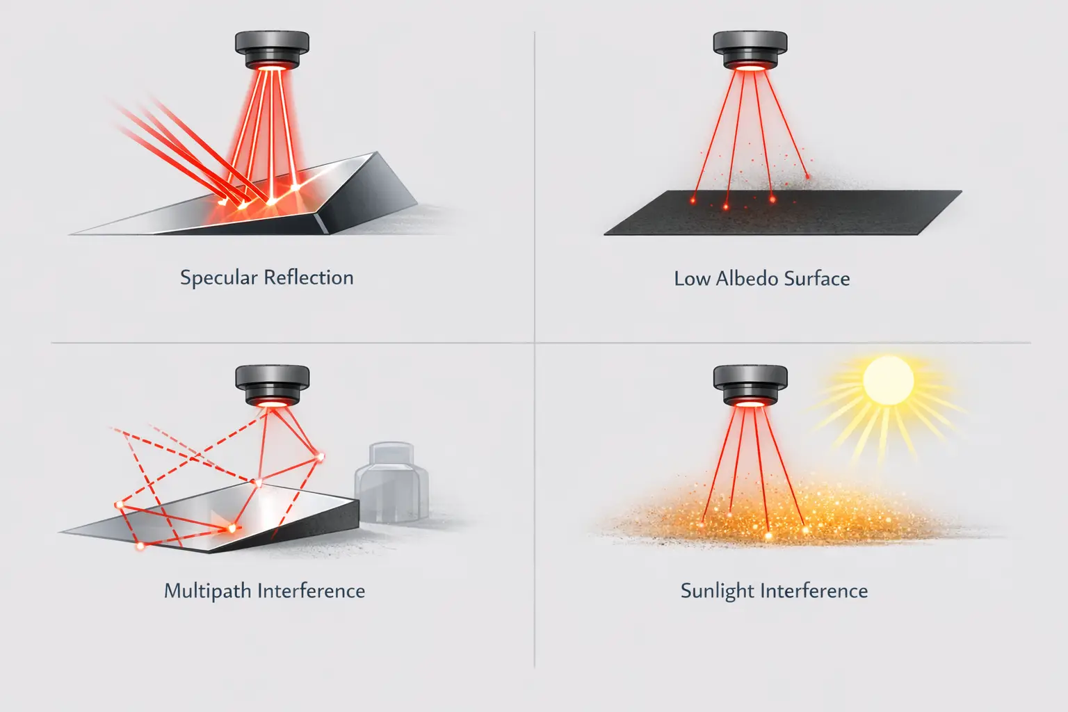
Error Sources (ambient light, multipath, materials)
Depth errors in NIR systems typically arise from scene-dependent signal formation rather than from a single global “accuracy” constant. For iToF sensors, peer-reviewed discussions of ToF depth errors describe the influence of ambient illumination, surface reflectance properties, and multipath interference (MPI), where indirect light paths (for example, in corners or concavities) bias phase measurements and produce systematic depth artifacts. [12] Stereo and structured-light systems similarly degrade on surfaces that do not preserve the projected pattern (for example, specular highlights, translucency, or low albedo in NIR), and they can be limited by exposure and motion-induced mismatch, which appears as temporal instability in the depth map. Datasheet-style quality metrics attempt to summarize these behaviors in controlled conditions; Intel RealSense D400-series depth quality lists Z-accuracy (absolute error) ≤ 2%, fill rate ≥ 99%, and temporal noise (pixel) ≤ 1%. [1] Volumetric accuracy, published more often for metrology-oriented scanners than for depth cameras, expresses accumulation of errors over volume or length; EinScan Libre specifies volumetric accuracy up to 0.04 + 0.06 mm/m rather than a single constant value. [7]
Low-Light Scanning and Sunlight Interference
Low-light scanning is often a usability benefit of active NIR systems: because the device emits its own illumination, it can operate when visible-light cameras struggle to expose or track features. Apple states Face ID is designed to work “even in total darkness,” reflecting the general advantage of active NIR illumination for robust sensing without visible lighting. [9] This does not imply that all infrared 3D scanner modalities maintain constant depth quality across lighting conditions, because exposure control, signal-to-noise ratio, and algorithm confidence thresholds can still change with scene reflectance and range.
Direct sunlight can degrade an infrared 3D scanner because solar radiation contains NIR energy that raises background levels and can saturate sensors or reduce modulation contrast, producing ambient IR / sunlight interference. In manufacturer positioning, this is sometimes addressed as a mode-level tradeoff rather than a guarantee; EinScan Libre describes IR Rapid Mode as “less sensitive to ambient light,” which may be relevant for uncontrolled illumination but is not a universal performance bound. [7] No reliable figure found for a universal “low-light accuracy” value across IR scanners, and published sources do not provide a single lux threshold that generalizes across device classes, sensor exposures, and materials. [12]
Representative Devices and Modes (mandatory Comparison Table)
Published specifications for IR 3D scanners vary in both form and intent: embedded depth cameras often provide mode tables (resolution, FOV, frame rate, and Min‑Z), while handheld scanning products may emphasize volumetric accuracy, capture window size, and point throughput. Intel’s RealSense D400-series datasheet, for example, provides emitter wavelength and laser compliance statements alongside depth-quality metrics and mode-dependent Min‑Z. [1] Conversely, peer-reviewed evaluations of iToF devices such as Azure Kinect DK commonly report mode-dependent FOV and operating range and describe frequency-domain ToF behavior via modulation frequency. [3]
Device landscape changes can also affect how “reference” specifications are interpreted in practice. Microsoft’s announcement that it would end production of Azure Kinect Developer Kit on Aug 17, 2023, and transfer technology to a partner ecosystem encouraged developers to treat Azure Kinect DK measurements as representative of an iToF class rather than as a guaranteed long-term supply baseline. [2] In parallel, mobile and accessory depth sensors (such as iPad Pro LiDAR units and Structure Sensor attachments) are often described via application constraints (range, integration form factor, and API availability) more than via metrology-grade calibration disclosures. [5][6]
Published “error term” statements also differ by publisher and test condition. As an example of vendor-published iToF error expressions, Orbbec’s comparison page (discussing identical modes relative to Azure Kinect DK under stated conditions) notes illumination wavelength as 850 nm in a footnote and lists random error standard deviation ≤ 17 mm and typical system error < 11 mm + 0.1% of distance; these statements are attributed to Orbbec’s published comparison text rather than to a Microsoft datasheet. [4]
| Device | Depth modality | IR emitter type | Wavelength (if published) | Range / working distance | Depth/scan resolution | Accuracy expression (as published) | FOV | Frame rate / points/s | Notes |
|---|---|---|---|---|---|---|---|---|---|
| Intel RealSense D4xx family (D435 category FOV) | Active stereo (with optional infrared projector) | Infrared projector (laser) | 850 nm ± 10 nm nominal @ 20°C | Min‑Z examples by mode: 450 mm (1280×720) and 310 mm (848×480) for D400/D410/D415; 280 mm (1280×720) and 195 mm (848×480) for D420/D430 | Depth stream formats include Z16; example resolutions 1280×720 and 848×480 | Z-accuracy (absolute error) ≤ 2%; fill rate ≥ 99%; temporal noise (pixel) ≤ 1% | HFOV 86°, VFOV 57°, DFOV 94° (HD 16:9, D420/D430/D435/D435i category) | Example depth FPS: 1280×720 at 6/15/30; 848×480 at 6/15/30/60/90 | Projector optical power (standard): 360 mW average, 440 mW peak; (wide): 360 mW average, 4.25 W peak; laser compliance stated as Class 1 to IEC 60825-1:2007 and IEC 60825-1:2014 |
| Azure Kinect DK | iToF | NIR ToF illumination (device class) | 850 nm (in Orbbec comparison conditions) | WFOV: 0.25–2.21 m (unbinned), 0.25–2.88 m (binned); NFOV: 0.50–3.86 m (unbinned), 0.50–5.46 m (binned) | Not specified in cited sources | Random error std. dev. ≤ 17 mm; typical system error < 11 mm + 0.1% of distance (Orbbec comparison text) | WFOV: 120° × 120° (max); NFOV: 75° × 65° (max) | Not specified in cited sources | ToF modulation frequency reported as 200–320 MHz; Microsoft announced end of production Aug 17, 2023 |
| Structure Sensor (Mark II) | NIR depth sensor (manufacturer specification; modality not detailed on cited spec page) | IR illumination (device class) | No reliable figure found | Recommended range 0.3 m to 5 m+ | Depth resolution 1280 × 960 | No reliable figure found (depth accuracy not published in cited sources) | FOV 59 × 46 | Not specified in cited sources | Often used as an accessory sensor class where range/FOV are emphasized over metrology expressions |
| EinScan Libre (IR Rapid Mode) | Active NIR scanning mode (IR Rapid) | IR VCSEL (vertical-cavity surface-emitting laser) | Not specified on cited page | Working distance up to 1.5 m | Not specified in cited sources | Volumetric accuracy up to 0.04 + 0.06 mm/m | FOV 983 × 979 mm | Not specified in cited sources | Example of a product family that publishes volumetric accuracy for larger-area scanning |
| iPad Pro LiDAR | Mobile LiDAR depth sensor (device class) | Not specified in cited sources | No reliable figure found | Range reported as restricted to 5 m | Not specified in cited sources | Apple does not specify LiDAR or TrueDepth accuracy as a hardware spec | Not specified in cited sources | Not specified in cited sources | Mobile constraints often emphasize coverage and integration; emitter wavelength not published in cited sources |
Applications (robotics, AR, body scanning, metrology)
In robotics and spatial computing, IR 3D scanner selection is often constrained by range, coverage, and frame-to-frame stability rather than by a single “accuracy” number. For indoor navigation and obstacle avoidance, iToF modes can trade FOV for maximum range, as characterized by Azure Kinect DK WFOV and NFOV operating ranges and their corresponding maximum FOV values. [3] For integration into mobile or head-mounted workflows, the NIR depth camera may be evaluated primarily by the reliability of depth maps and point clouds in low light and by susceptibility to ambient IR when transitioning near windows or outdoors. [12]
Body scanning, object digitization, and light metrology tasks often prioritize predictable coverage and repeatability over real-time tracking alone. The Structure Sensor (Mark II) publishes a recommended range of 0.3 m to 5 m+ and an FOV of 59 × 46, which can be mapped to room-scale capture and close-range scanning depending on reconstruction software and tracking assumptions. [6] Hybrid handheld systems may incorporate both visible and IR illumination; EinScan H2 lists a light source of White LED / Infrared VCSEL and a maximum FOV up to 780 × 900 mm in IR mode, illustrating how IR modes can be positioned for larger capture windows while visible-light modes can be used for different surface conditions. [8]
Safety, Compliance, and Operational Constraints
“IR” does not automatically mean “eye-safe”; safety depends on emitter characteristics, exposure conditions, and the applicable IEC 60825-1 laser safety class stated by the manufacturer. Intel’s RealSense D400-series datasheet specifies laser compliance as Class 1 and cites IEC 60825-1:2007 and IEC 60825-1:2014 for its IR projector configurations. [1] The same datasheet lists projector optical power values (for example, 360 mW average with 440 mW peak for a standard projector configuration, and 360 mW average with 4.25 W peak for a wide projector configuration), and these figures are typically treated as emitter specifications rather than as user-tunable “laser power settings” in software. [1] System integrators still commonly consider enclosure design, minimum viewing distance assumptions, and regulatory labeling as part of deploying an infrared 3D scanner in products or public environments. [1]
Practical Workflow Notes (data products and formats)
IR 3D scanner pipelines usually produce a depth map (a per-pixel distance image) and often an IR intensity image; software can reproject depth into a point cloud and later fuse multiple frames into a mesh. Mode choice (resolution, FOV, and exposure) affects reconstruction stability and failure rates; for Intel RealSense D400-series, the datasheet lists Z16 depth modes including example frame rates of 6/15/30 FPS at 1280×720 and 6/15/30/60/90 FPS at 848×480. [1]
Common capture problems are often material- or scene-dependent rather than device-specific, and mitigation typically involves changing viewpoint, exposure, or modality (for example, switching between iToF and active stereo where available), rather than expecting a universal “IR works everywhere” behavior. [12]
- Common IR scanning failure modes
- Specular surfaces that distort or saturate returns.
- Dark or low-albedo surfaces in NIR that reduce signal.
- Multipath interference (MPI) in corners and concave geometry.
- Outdoor sunlight conditions that increase ambient IR background.
- Motion blur or temporal instability during handheld capture.
- IR interference from other emitters operating nearby.
- Metrics to report for any IR 3D scanner
- Wavelength (if published).
- IEC 60825-1 laser safety class (if applicable).
- Minimum range / Min‑Z (and the mode assumptions).
- Range or working distance (and the tested mode).
- Field of view (FOV) and aspect ratio for each depth mode.
- Depth resolution (depth map dimensions or stated depth resolution).
- Frame rate (FPS) or points/s (and whether it is per-frame or aggregated).
- Accuracy expression as published (percent-of-distance, absolute, or volumetric accuracy).
- Calibration assumptions (temperature, target type, and whether factory or user calibration is required).
- Data products and interfaces (depth map format, point cloud availability, USB or other transport).
FAQ
What is an IR 3D scanner, and how does an infrared scan differ from visible-light 3D scanning?
An IR 3D scanner is a near-infrared (NIR) depth camera that estimates geometry using non-visible illumination and an IR-sensitive sensor, producing depth maps and point clouds. [1] An infrared scan in this sense is distinct from thermal imaging: it measures distance, not temperature. [6] In active stereo and structured-light systems, the device can project a non-visible IR pattern to create texture for depth estimation, whereas visible-light 3D scanning often relies on RGB texture, photogrammetry, or visible structured light. [1]
Does low-light scanning improve accuracy, or only usability? (keyword: low-light scanning)
Low-light scanning primarily improves usability and robustness by ensuring the scene is illuminated for the depth method, rather than guaranteeing better absolute accuracy. Apple’s statement that Face ID works “even in total darkness” is an example of intended operation in the absence of visible light, not a published precision metric. [9] No reliable figure found for a universal accuracy gain in darkness across infrared 3D scanner designs, because accuracy depends on modality, exposure, reflectance, and algorithm confidence thresholds. [12]
What is Min‑Z in an infrared 3D scanner, and why does it depend on resolution? (expert-level)
Minimum range / Min‑Z is the nearest distance at which a device can produce valid depth for a specific mode, and it often varies with depth resolution and processing configuration. Intel RealSense D400-series examples include Min‑Z values of 450 mm at 1280×720 and 310 mm at 848×480 for D400/D410/D415, and 280 mm at 1280×720 and 195 mm at 848×480 for D420/D430. [1] The dependence on resolution reflects that disparity search limits, projector pattern scale, and per-pixel geometry constraints change with mode, so a depth map may become unreliable at close range even if the IR image is well exposed. [1]
How do WFOV and NFOV modes change performance in iToF cameras like Azure Kinect DK?
WFOV and NFOV are iToF mode families that trade angular coverage against range and sampling behavior. A peer-reviewed Azure Kinect DK evaluation reports maximum FOV values of 120° × 120° for WFOV and 75° × 65° for NFOV. [3] The same evaluation reports different operating ranges by mode and binning, including WFOV ranges of 0.25–2.21 m (unbinned) and 0.25–2.88 m (binned), and NFOV ranges of 0.50–3.86 m (unbinned) and 0.50–5.46 m (binned). [3]
What is volumetric accuracy, and why do some scanners publish “0.04 + 0.06 mm/m” instead of a single accuracy number? (expert-level)
Volumetric accuracy expresses how geometric error accumulates over a volume or length scale, rather than describing a single-point depth deviation at one distance. EinScan Libre specifies volumetric accuracy up to 0.04 + 0.06 mm/m, which is a scale-dependent expression rather than a constant. [7] This format is commonly used in handheld scanning contexts where alignment, tracking drift, and calibration errors can compound as scan size increases, making a single “accuracy at one point” less descriptive of full-object results. [7]
Are infrared scanners always eye-safe?
Not necessarily; eye safety depends on the emitter design and the stated IEC 60825-1 laser safety class. Intel’s RealSense D400-series datasheet specifies Class 1 laser compliance and cites IEC 60825-1:2007 and IEC 60825-1:2014. [1] Users and integrators typically rely on device labeling and manufacturer documentation for the specific model and operating configuration, rather than assuming that any infrared 3D scanner is eye-safe by default. [1]
Sources
- Intel RealSense D400 Series Datasheet
- Microsoft’s Azure Kinect Developer Kit technology transfers to partner ecosystem (end of production announcement)
- Evaluation of the Azure Kinect DK (modes, ranges, FOV, modulation frequency)
- Orbbec documentation: Comparison with Azure Kinect DK
- Paper summarizing iPad Pro LiDAR range restriction to 5 m
- Structure Sensor (Mark II) specifications
- SHINING 3D EinScan Libre product page (IR VCSEL, IR Rapid Mode specs, volumetric accuracy)
- SHINING 3D EinScan H2 product page (hybrid light source, IR mode FOV, points/s)
- Apple Support: Face ID security and “even in total darkness” statement
- MDPI paper noting Apple does not specify LiDAR or TrueDepth accuracy as a hardware spec
- arXiv: Comparison of Kinect structured-light vs ToF (conceptual framing)
- MDPI Sensors paper on ToF depth errors (lighting/material factors, MPI discussion)
- Business Wire: PrimeSense Selected by Microsoft for Project Natal (2010 announcement)