
Summary
A blue light 3D scanner is a structured light 3D scanning system that projects a calibrated pattern, often fringe projection, in blue wavelengths and uses cameras to triangulate surface geometry from the pattern’s deformation. [1] In vendor specifications, “accuracy” typically refers to a test-dependent dimensional error after calibration rather than mesh detail; for example, the Artec Spider II specifies a 450 nm LED structured-light source alongside an accuracy of up to 0.05 mm. [6]
What Is a Blue Light 3D Scanner? (Scanner-types context)
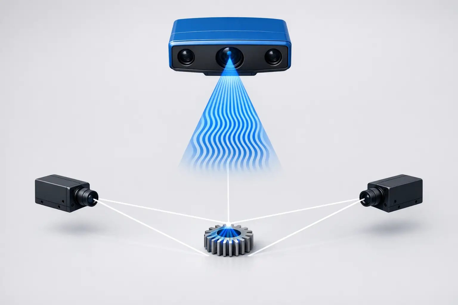
In optical metrology, structured light scanning projects a precisely calibrated pattern of white or blue light onto a surface, then one or more cameras observe the pattern distortion to reconstruct 3D shape. [1] “Blue light scanners” commonly refer to blue fringe projection systems (structured light with projected fringe patterns) implemented with a projector and stereo camera geometry (stereo triangulation), where calibration links pixel measurements to 3D coordinates.
Within “blue light 3D scanner” search intent, it is also common to encounter blue laser scanners that use coherent blue laser lines rather than projected LED fringes. The SHINING 3D OptimScan Q12 specifies a Blue LED light source and publishes separate accuracy and point-distance values for two scan ranges, consistent with a fringe-projection-style inspection system. [11] By contrast, the SHINING 3D FreeScan UE Pro is specified as a handheld laser scanner and publishes a scan speed of 1,850,000 points/s and a volumetric accuracy expression (with photogrammetry), reflecting a different data-acquisition model than full-field fringe projection. [13]
Historical Background (Origins of structured light and fringe projection)
Early structured-light measurement literature includes “Surface measurement by space-encoded projected beam systems,” published in Computer Graphics and Image Processing 18(1) in 1982. [2] Fringe projection profilometry methods for extracting shape from fringe patterns were further developed in “Fourier transform profilometry for the automatic measurement of 3-D object shapes” (Takeda; Mutoh), published in Applied Optics in 1983. [3] Phase-measuring approaches closely related to phase shifting were described in “Automated phase-measuring profilometry of 3-D diffuse objects” (Srinivasan; Liu; Halioua), published in Applied Optics in 1984. [3]
How Blue Fringe Projection Works (Technical principle)
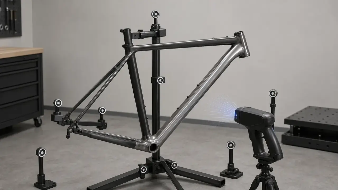
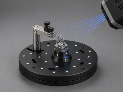
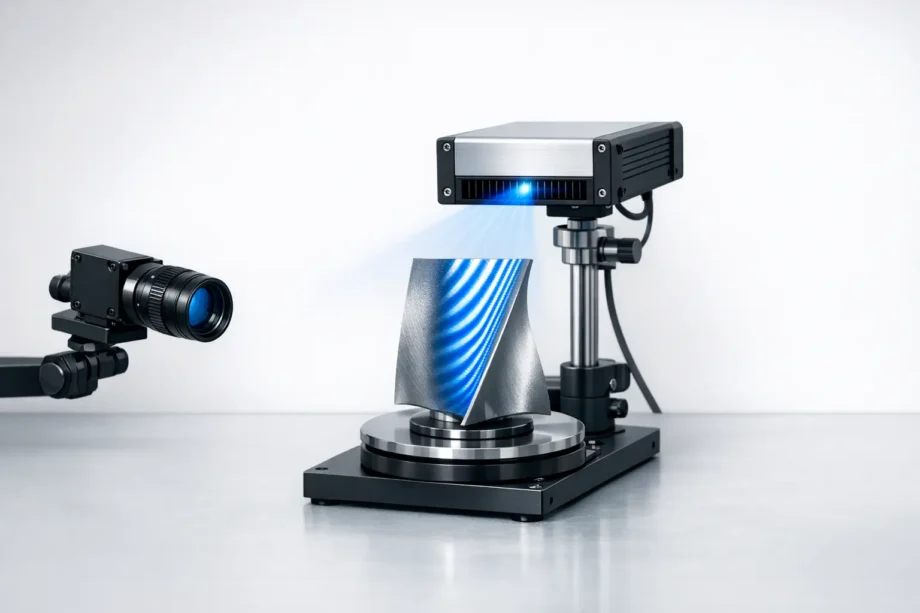
In blue fringe projection, a projector emits a sequence of spatial intensity patterns (often sinusoidal fringes) across the part, and cameras record images of those fringes from different viewpoints. In phase-shifting implementations, multiple projected patterns with known phase offsets are used so that phase can be decoded per pixel, yielding dense correspondence between camera pixels and projector coordinates. The resulting phase map is converted into 3D points via a calibrated stereo triangulation model that accounts for lens distortion, camera-projector geometry, and the working distance used during measurement. In product terms, this workflow is typically described as “structured blue light” full-field capture, and the ZEISS ATOS 5 brochure states that ATOS sensors operate with structured blue light and that an individual measurement can consist of up to 12 million measuring points. [8]
Manufacturers summarize the output and optical configuration using a small set of measurable descriptors: points per scan (or measuring points), point distance (often used as a resolution proxy for sampling density), measuring area (field of view), and working distance. The ZEISS ATOS Q is specified with either 8 million or 12 million points per scan, point distance ranges of 0.04–0.15 mm (8M) and 0.03–0.12 mm (12M), and a working distance of 490 mm. [7] The same source lists measuring areas from 100×70 to 500×370 mm² and “measuring volumes” of 50, 100, 170, 270, 350, and 500 (units as presented), illustrating how a single sensor family can be configured for different part sizes and sampling densities. [7]
Technical Performance: Accuracy, Resolution, and Speed (Not interchangeable)
In vendor literature for high-resolution 3D scanners, accuracy, resolution (often published as point distance or “3D resolution”), and speed/throughput describe different aspects of performance and should not be treated as interchangeable. Standards-focused guidance emphasizes that “accuracy” claims depend on the acceptance test used and the systematic error sensitivities of that test, motivating the need to interpret published numbers within a stated evaluation framework. [4] As an example of metric separation on a handheld blue-light device, Artec Space Spider publishes 3D accuracy up to 0.05 mm and 3D resolution up to 0.1 mm, while also listing a 3D reconstruction rate up to 7.5 FPS (frames per second) and data processing up to one million points per second. [5] Artec Spider II publishes accuracy up to 0.05 mm and resolution up to 0.05 mm, while separately listing data acquisition speed up to 8 mln points/s, real-time fusion up to 30 fps, and a 450 nm LED structured-light source. [6] For fixed inspection-class systems, SHINING 3D OptimScan Q12 publishes accuracy of 0.015 mm (large range) and 0.005 mm (small range) and point distance of 0.1 mm (large) and 0.04 mm (small), demonstrating how a single device can present multiple “accuracy-like” values tied to different measuring fields and standoff distances. [11] Compact fringe projection systems similarly expose sampling-density tradeoffs; the ZEISS GOM Scan 1 publishes point distance values of 0.037 mm, 0.060 mm, and 0.129 mm across its measuring-area configurations. [9]
Measurement Standards and Acceptance Tests (VDI/VDE 2634, ISO 10360-13)
For optical 3D scanners, measurement standards formalize acceptance tests intended to characterize performance in a repeatable way rather than guaranteeing a single universal “accuracy” value across all part geometries, materials, and workflows. The National Institute of Standards and Technology (NIST) discusses performance evaluation tests for structured light systems under VDI/VDE 2634-2 and ISO 10360-13, and frames these methods in terms of what systematic errors and sensitivities the tests can reveal. [4] In practice, this means accuracy figures are best interpreted as conditional on the stated test method, calibration state, measuring volume, and environmental conditions, rather than as a direct substitute for point distance (sampling) or for volumetric accuracy expressions used in some metrology workflows.
Comparison Table: Popular Blue Light Scanner Examples (Cited specs only)
The following comparison aggregates only the specifications explicitly published in the cited sources and keeps “accuracy,” “point distance,” and throughput terms separate. Where a metric is not published in the cited documentation, the table lists “No reliable figure found” rather than inferring values from marketing descriptions or from unrelated configurations. [4]
| Device | Light source (Blue LED / blue laser lines / wavelength if published) | Single-point accuracy (as published) | Volumetric accuracy (as published) | Point distance / resolution (as published) | Points per scan or points per second (as published) | Measuring area / scan range / working distance (as published) | Notes on test method (standard mentioned or not) |
|---|---|---|---|---|---|---|---|
| ZEISS ATOS Q | No reliable figure found | No reliable figure found | No reliable figure found | 0.04–0.15 mm (8M) or 0.03–0.12 mm (12M). [7] | 8 million or 12 million points per scan. [7] | Measuring area 100×70 to 500×370 mm²; working distance 490 mm. [7] | No standard stated in cited source. |
| ZEISS GOM Scan 1 | Blue light (440–465 nm). [10] | No reliable figure found | No reliable figure found | 0.037 / 0.060 / 0.129 mm. [9] | 6 million points per scan. [9] | Measuring area 100×65 / 200×125 / 400×250 mm²; working distance 400 / 450 / 500 mm (configuration-dependent). [9] | Reseller-published specification; no standard stated in cited source. [9] |
| Artec Spider II | 3D structured-light source, 450 nm LED. [6] | Up to 0.05 mm. [6] | No reliable figure found | Up to 0.05 mm. [6] | Up to 8 mln points/s; real-time fusion up to 30 fps. [6] | No reliable figure found | No standard stated in cited source. |
| Artec Space Spider | Based on blue light technology (wavelength not specified). [5] | Up to 0.05 mm. [5] | No reliable figure found | Up to 0.1 mm. [5] | Data processing up to one million points/s; 3D reconstruction rate up to 7.5 FPS. [5] | No reliable figure found | No standard stated in cited source. |
| SHINING 3D OptimScan Q12 | Blue LED. [11] | 0.015 mm (large range) or 0.005 mm (small range). [11] | No reliable figure found | 0.1 mm (large) or 0.04 mm (small). [11] | No reliable figure found | Scan range 430×300 mm (large) or 160×110 mm (small); working distance 590 mm (large) or 210 mm (small). [11] | No standard stated in cited source. |
| SHINING 3D OptimScan 5M Plus | Blue light (LED). [12] | Single shot accuracy 0.005 mm. [12] | No reliable figure found | Point distance up to 0.04 mm. [12] | Scan speed ≤1.5 s. [12] | Working distance 560 mm. [12] | No standard stated in cited source. |
Across these examples, point distance and points-per-capture figures primarily describe sampling density, while “accuracy” claims are published as separate values that may reflect different test artifacts, fields of view, and measurement distances. [4] Throughput is also described inconsistently across devices (for example, points per scan on ATOS Q versus points per second on Artec Spider II versus seconds per shot on OptimScan 5M Plus), so comparisons typically require mapping published specs to a specific inspection workflow and acceptance test. [7][6][12]
Applications and Use Cases (When blue light is selected)
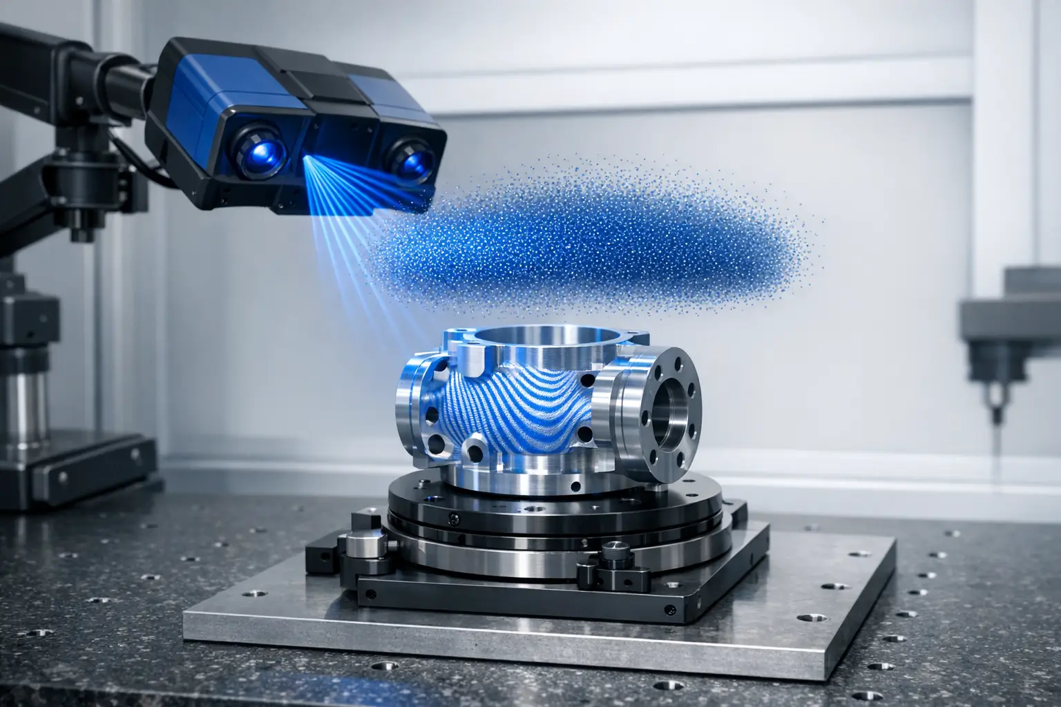
Blue fringe projection and other structured-blue-light systems are commonly selected for full-field inspection, reverse engineering, and dimensional verification where dense surface sampling is needed across a measuring area. In metrology-oriented deployments, the workflow emphasis is often on repeatable measurement under a defined acceptance test regime, rather than on visual mesh detail alone. [4] The ZEISS ATOS 5 brochure presents ATOS sensors as structured blue light systems intended for production metrology contexts and includes additive manufacturing among the application areas discussed in the brochure material. [8]
Procurement Checklist (Scanner selection criteria)
Selection of a blue light 3D scanner typically involves trading field of view against sampling density and setup constraints. For example, the ZEISS ATOS Q publishes point distance ranges down to 0.03 mm (12M) and up to 0.15 mm (8M), but these values are tied to specific configurations and measuring areas. [7] Similarly, the ZEISS GOM Scan 1 publishes three measuring areas (100×65, 200×125, 400×250 mm²) with corresponding working distances (400, 450, 500 mm), which affects accessibility around features and fixturing options. [9] Systems like the SHINING 3D OptimScan Q12 explicitly separate “large” and “small” scan ranges with different working distances and published accuracy/point distance values, which can be used to plan multi-scale inspection strategies. [11]
A procurement review commonly also considers how published performance figures are validated (for example, whether the vendor provides results under VDI/VDE 2634-2 or ISO 10360-13 acceptance tests) and how the scanner integrates into a metrology workflow that includes calibration, alignment, and reporting. [4] Hardware details can matter when comparing scanner types; for example, Artec Spider II specifies a 450 nm LED structured-light source, which indicates a narrow spectral band compared with white-light projection even when the manufacturer does not publish an ambient-light immunity specification. [6]
- Required smallest feature size — map to point distance and optics (for example, ATOS Q point distance 0.03–0.15 mm depending on configuration, and GOM Scan 1 point distance 0.037–0.129 mm depending on measuring area). [7][9]
- Part size and accessibility — map to measuring area and working distance (for example, GOM Scan 1 measuring areas up to 400×250 mm² with working distances up to 500 mm, and OptimScan Q12 scan ranges up to 430×300 mm with a 590 mm working distance in its large-range setup). [9][11]
- Required dimensional tolerances — map to acceptance test regime (VDI/VDE / ISO) and the stated test conditions used to publish accuracy. [4]
- Surface properties — reflectivity, dark materials, translucent plastics
- Production environment — ambient light and vibration considerations
- Metrology workflow — alignment strategy, photogrammetry, inspection software outputs
FAQ
What is a blue light 3D scanner (blue light 3D) and how is it different from a blue laser scanner?
A blue light 3D scanner is typically a structured light system that projects a calibrated pattern (often fringes) and reconstructs 3D shape from how cameras observe the pattern’s deformation. [1] In contrast, a blue laser scanner acquires data using laser illumination (often lines) and reports throughput in terms such as points/s; for example, SHINING 3D FreeScan UE Pro specifies 1,850,000 points/s, while SHINING 3D OptimScan Q12 specifies a Blue LED light source consistent with full-field structured light capture. [13][11]
How do manufacturers define blue light accuracy, and why do “accuracy” numbers differ across brands?
Accuracy is typically published as a test-dependent error bound under particular conditions rather than as a universal guarantee across all part geometries and measurement volumes, which is why acceptance tests and error sensitivities matter. [4] Published examples also reflect different scanner classes and configurations: Artec Space Spider specifies 3D accuracy up to 0.05 mm, while SHINING 3D OptimScan Q12 specifies accuracy of 0.005 mm in its small scan range and 0.015 mm in its large scan range. [5][11]
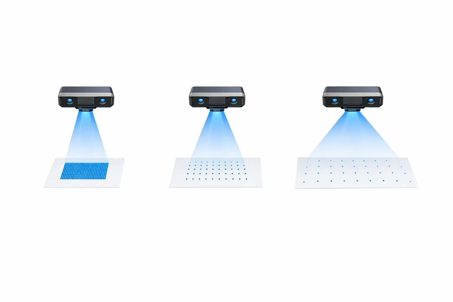
What does “point distance” mean on a high-resolution scanner, and how does it relate to mesh detail?
Point distance is commonly published as a sampling-spacing metric associated with the density of measured points across the surface, and it is often used as a proxy for the smallest geometric detail that can be represented in the resulting point cloud or mesh. The ZEISS ATOS Q lists point distance ranges of 0.04–0.15 mm (8M) and 0.03–0.12 mm (12M), while the ZEISS GOM Scan 1 lists point distances of 0.037 mm, 0.060 mm, and 0.129 mm across its measuring-area configurations. [7][9]
Is blue light scanning affected by ambient light, and how do some systems mitigate it?
No reliable primary explanation found in the cited manufacturer pages and manuals for a general statement that blue structured light is intrinsically immune to ambient light. In practice, optical scanning is generally treated as sensitive to uncontrolled illumination and reflections, so setups often rely on controlled lighting, stable exposure settings, and careful surface preparation where required.
Expert — What acceptance tests are used for optical 3D scanners (VDI/VDE 2634, ISO 10360-13), and what do they actually detect?
VDI/VDE 2634-2 and ISO 10360-13 are acceptance-test frameworks used to evaluate structured light scanner performance using defined procedures, and they are intended to characterize performance and reveal systematic error behaviors under test conditions. [4] NIST’s discussion emphasizes that different tests can have different sensitivities to systematic errors, which is one reason vendor “accuracy” figures may not be directly comparable without the test context and measuring volume. [4]
Expert — When should you prioritize points per scan, points per second, or scan time per shot?
Points per scan is most relevant for full-field systems where each capture returns a dense measurement field; for example, ZEISS ATOS Q specifies 8 million or 12 million points per scan. [7] Points per second is most relevant for continuous acquisition workflows and is often paired with frame-rate terms; for example, Artec Spider II lists data acquisition speed up to 8 mln points/s and real-time fusion up to 30 fps. [6] Scan time per shot is most relevant when cycle time is dominated by discrete captures; for example, SHINING 3D OptimScan 5M Plus lists scan speed ≤1.5 s. [12]
Sources
- Artec 3D Learning Center — Structured light 3D scanning
- CIR/NII — “Surface measurement by space-encoded projected beam systems” (1982) record
- OSTI.GOV — Bibliographic record including profilometry papers (Takeda & Mutoh 1983; Srinivasan et al. 1984)
- NIST — VDI/VDE 2634-2 and ISO 10360-13 performance evaluation tests and systematic errors
- Artec 3D — Artec Space Spider (archived “old/spider” page)
- Artec 3D — Artec Spider II specifications
- ZEISS Metrology — ATOS Q product page
- ZEISS — ATOS 5 brochure (PDF)
- GoMeasure3D (reseller) — ZEISS GOM Scan 1 specifications
- ManualsLib — ZEISS GOM Scan 1 manual (secondary host)
- SHINING 3D — OptimScan Q12 product page
- SHINING 3D — OptimScan 5M Plus product page
- SHINING 3D — FreeScan UE Pro product page