Summary (mandatory)
CoreXY is a belt-driven Cartesian X–Y motion architecture used in fused filament fabrication (FFF) / fused deposition modeling (FDM) 3D printers in which two typically stationary motors drive a coupled gantry, with firmware often mapping positions as A = X + Y and B = X - Y (with Z independent). [1] It is associated with high-speed 3D printer designs because keeping motors off the moving toolhead can reduce moving mass and inertia in parallel belt arrangements, though overall performance remains limited by mechanics and extrusion. [2] The concept is commonly associated with the CoreXY project site, which includes the attribution “© 2012 Ilan E. Moyer.” [3]
Historical Background (mandatory)
CoreXY is most often discussed as a published motion-system concept rather than a single branded product line. The CoreXY project site carries a copyright attribution to Ilan E. Moyer dated 2012, but this is typically treated as publication attribution rather than definitive proof of sole invention in the broader engineering sense. [3] Early hobbyist documentation and diagrams were widely circulated through community references such as the RepRap wiki, which describes CoreXY and H-bot as Cartesian arrangements and distinguishes them on mechanical loading behavior. [2]
An early signal of mainstream firmware adoption appears in the Marlin code history: a commit message reading “Added CoreXY support (Thanks Ilan Moyer)” is shown as committed on Jul 14, 2012, attributed to Erik van der Zalm in the referenced repository mirror. [4] This type of firmware-level support is significant because it formalized the kinematic mapping and direction conventions needed for calibration, step generation, and axis homing in typical open-source printer stacks, supporting later popularization in hobby and prosumer printers. [1]
CoreXY Motion — Definition and Kinematics (Principles)
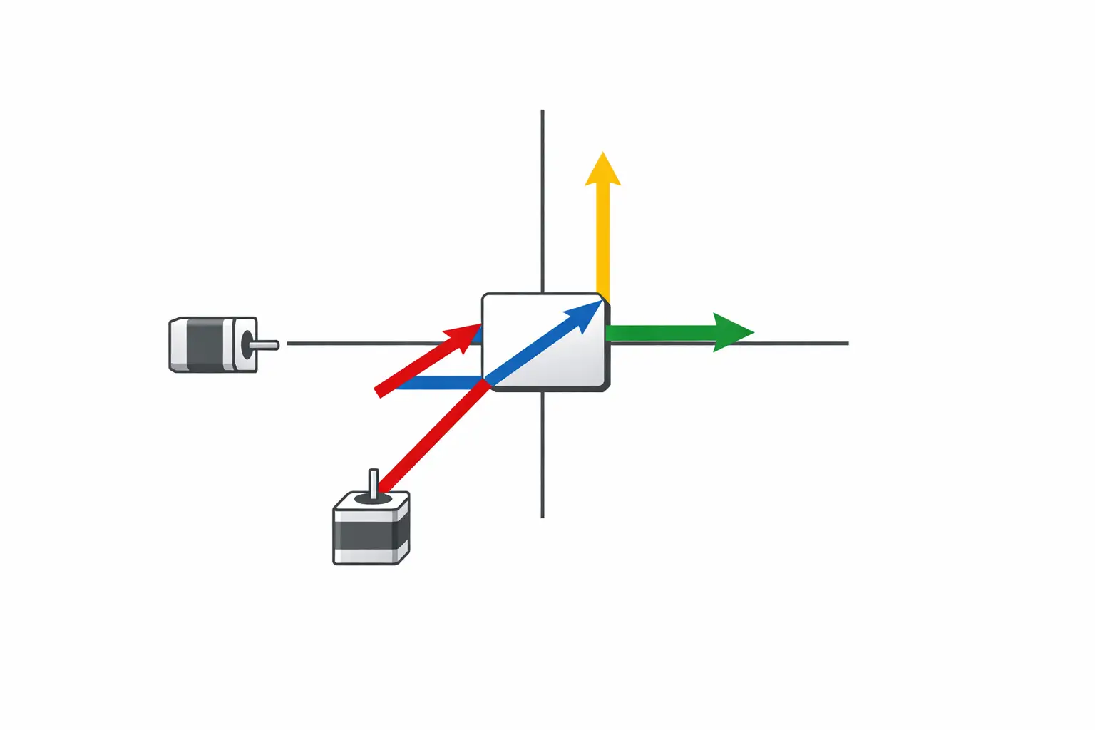
In implementation terms, CoreXY is defined by a coupled mapping between Cartesian coordinates and two belt-driven stepper axes. One common firmware expression is stepper_a_position = cartesian_x_position + cartesian_y_position and stepper_b_position = cartesian_x_position - cartesian_y_position, while stepper_z_position = cartesian_z_position. [1] With this mapping, pure X or pure Y motion generally requires coordinated motion of both motors, while turning only one motor produces a diagonal motion component in X and Y. [1] The coupling is a kinematic property of the belt path and pulley layout rather than a feature of the extruder (Bowden or direct drive) or the hot end.
Mechanical Architecture — Belt Paths, Idlers, and Load Equilibration
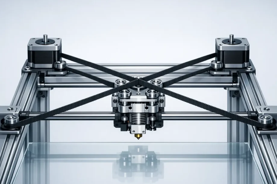
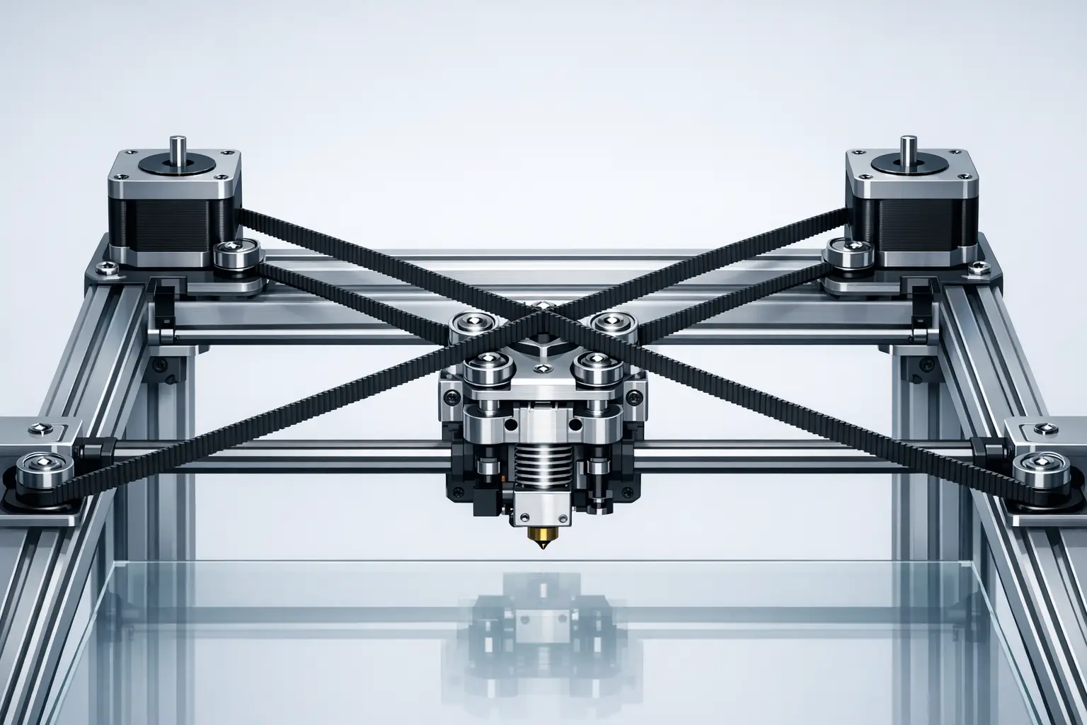
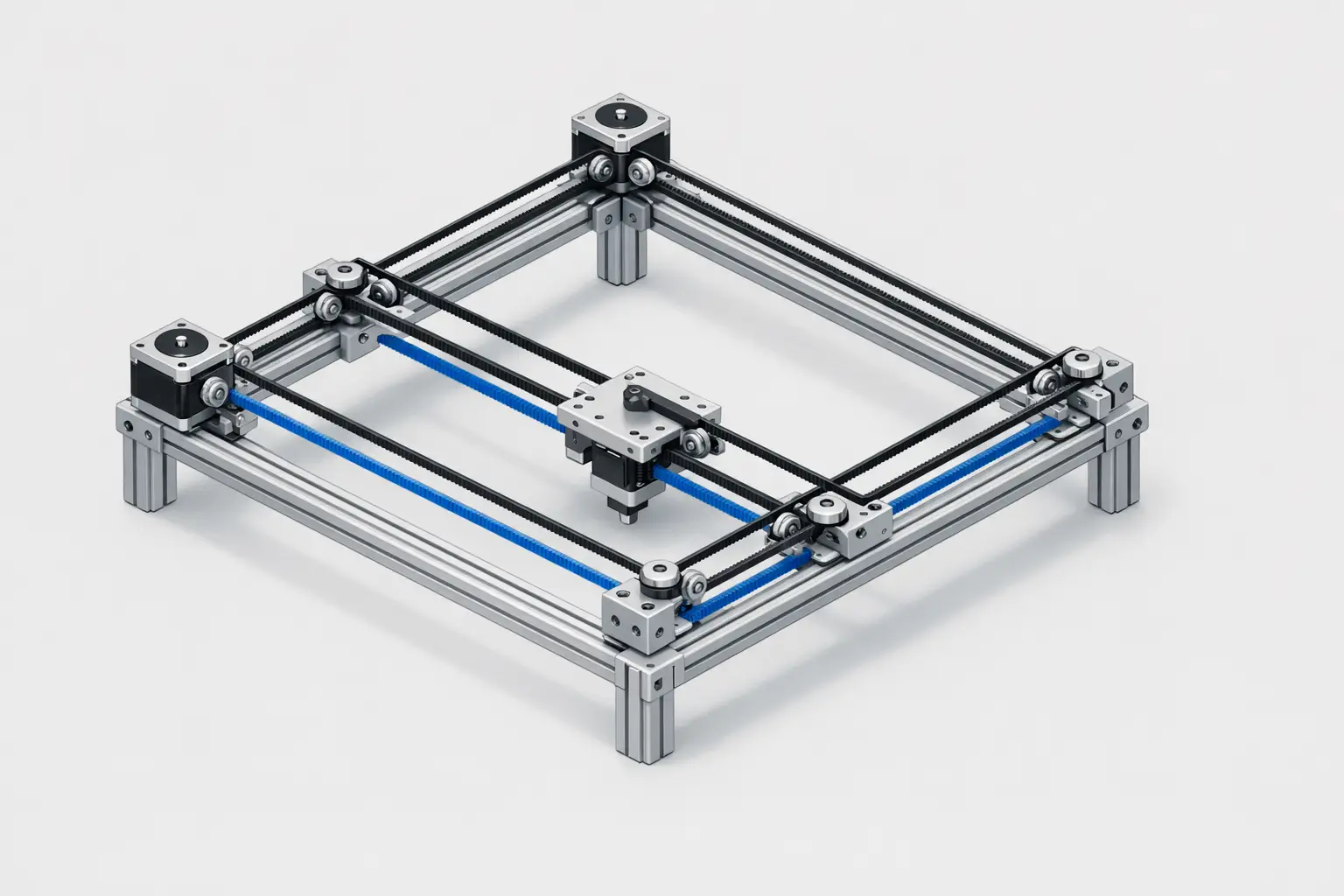
Mechanically, CoreXY is usually built from two continuous belts routed around an X–Y gantry with multiple idler pulleys so that the belts form a crossed-belt path that couples motor rotation into orthogonal toolhead travel. [2] Implementations often use stacked belt planes (two belt heights) or carefully spaced idlers to avoid belt interference while keeping the belt segments parallel where needed. [2] Because belt path geometry affects effective belt length, idler placement and alignment are treated as calibration-critical: idler pulley tilt or misalignment can introduce belt rubbing, varying friction, and asymmetric tension across the travel envelope.
A key design rationale for CoreXY is load equilibration relative to the simpler H-frame (H-bot) routing. The RepRap documentation describes CoreXY and H-bot as Cartesian arrangements, while noting that H-bot carriage loading tends to rotate around Z (a racking tendency) and that CoreXY adds pulleys to equilibrate loads so the carriage remains perpendicular without relying solely on carriage stiffness. [2] In academic descriptions of H-frame gantries, racking is treated as a parasitic torsional motion arising under high acceleration and speed, which can limit dynamic accuracy even when motors are frame-mounted. [10]
Technical Performance — Speed, Acceleration, and Precision Limits
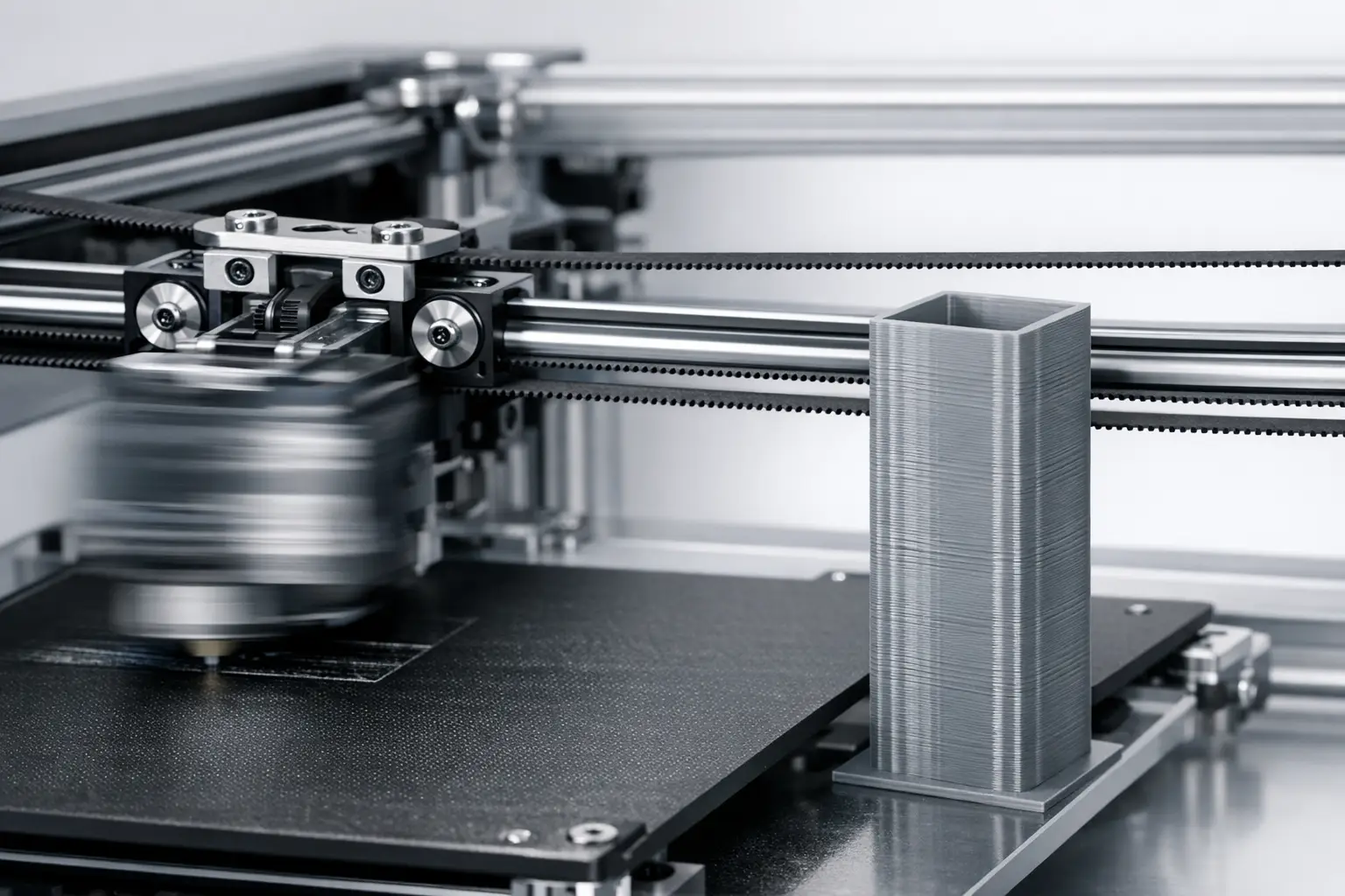
CoreXY is often selected for high travel speed and acceleration targets because its parallel arrangement can keep the X–Y drive motors stationary, reducing moving mass and inertia compared with architectures that carry motors on the gantry. [2] However, high-speed printing is typically constrained by resonance, belt tension stability, frame stiffness and squareness, and extrusion limits such as volumetric flow, in addition to motion planning and vibration control. Vendor specifications illustrate how these systems are marketed: the Bambu Lab X1 Carbon lists a maximum toolhead speed of 500 mm/s and maximum acceleration of 20 m/s², while the Creality K1 series is described with printing speed up to 600mm/s and acceleration 20000mm/s². [5][7] In practice, the racking mechanisms described for H-frame systems remain relevant as a cautionary comparison because racking-like frame/gantry torsion and belt-path asymmetry can still manifest as print artifacts such as ringing/ghosting when excitation coincides with structural modes. [10]
CoreXY in Commercial High-Speed FFF Printers — Device Examples
Published “max” values usually represent motion-system capability under favorable conditions (often closer to travel speed than typical print speed), while thermal limits (nozzle/bed temperatures) bound feasible material throughput and sustained volumetric flow. [5] In the Bambu Lab X1 ecosystem, CoreXY is explicitly named in a press-release style announcement that links a “CoreXY motion system” to 20,000 mm/s² acceleration and 500 mm/s speed, consistent with the X1 Carbon product listing. [6][5]
Large-format CoreXY implementations may emphasize build volume and platform engineering rather than only acceleration. Prusa explicitly frames the Original Prusa XL as “CoreXY” in a “First look” blog title and describes a segmented heatbed with 9×9 cm segments, while the product page specifies a 360×360×360 mm build volume and a segmented heatbed consisting of 16 individually controlled tiles, alongside a 0.05–0.30 mm layer height range. [9][8]
Table 2 — Spec Comparison (device examples)
| Metric | Bambu Lab X1 Carbon | Creality K1 series | Original Prusa XL |
|---|---|---|---|
| Motion system explicitly stated as CoreXY | “CoreXY motion system” stated in announcement. [6] | Described as “CoreXY.” [7] | “CoreXY” stated in Prusa blog title. [9] |
| Max speed | Max Speed of Tool Head 500 mm/s. [5] | Printing speed up to 600mm/s. [7] | No reliable figure found. |
| Max acceleration | Max Acceleration of Tool Head 20 m/s². [5] | Acceleration 20000mm/s². [7] | No reliable figure found. |
| Build volume | 256 × 256 × 256 mm³. [5] | Build volume up to 300300300 mm. [7] | 360×360×360 mm. [8] |
| Max nozzle temperature | 300 ℃. [5] | No reliable figure found. | 290 °C. [8] |
| Max bed temperature | 110℃@220V / 120℃@110V. [5] | No reliable figure found. | 120°C. [8] |
| Other published platform detail | Net weight 14.13kg. [5] | Printhead weight 190g; ramps to 600mm/s in 0.03s. [7] | Heatbed has 16 individually controlled tiles; segment size stated as 9×9 cm. [8][9] |
List A — Metrics to report for any “high-speed CoreXY printer” example (bulleted list):
- Max toolhead speed (mm/s) — if published
- Max toolhead acceleration (mm/s² or m/s²) — if published
- Build volume (mm)
- Max nozzle temperature (°C) and bed temperature (°C)
- Motion system explicitly stated as CoreXY — must be sourced (vendor, official blog, or manual)
- If any accuracy/precision spec is claimed — include the exact definition and test method, otherwise write “No reliable figure found”
List B — Disqualifying sourcing patterns (numbered list):
- “Micron accuracy” claims without a definition (repeatability vs positioning vs part tolerance)
- Blog-only performance metrics when a manufacturer spec exists and conflicts
- Any speed claim that omits whether it is print speed, travel speed, or a special mode
- Any claim that CoreXY “guarantees” better quality without noting stiffness, resonance, and extrusion limits
Comparison (mandatory table)
At a concept level, CoreXY, Cartesian, H-bot, and Delta differ primarily in kinematic coupling, where motor mass is located, and which failure modes dominate calibration and print artifacts. CoreXY and H-bot are both Cartesian arrangements with stationary motors and (typically) lower moving inertia than serial “stackup” arrangements, but H-bot is associated with racking under dynamic loading in both community descriptions and engineering literature. [2][10] Industrial belt-driven H-bot gantries outside printing also publish high operating speed and acceleration figures (5 m/s and 50 m/s²) with repeatability specified as ±0.1 mm, illustrating that similar belt-and-idler principles are used beyond hobby printers without implying identical print outcomes. [12]
Table 1 — Motion Architecture Comparison (conceptual properties + common failure modes)
| Architecture | Typical motor placement | Kinematic coupling | Common artifact risks and calibration complexity |
|---|---|---|---|
| CoreXY | Stationary X–Y motors on frame. [2] | Coupled X/Y; both motors participate in pure-axis moves. [1] | Belt tension balance, squareness, idler alignment; ringing/ghosting from resonance; reduced racking tendency relative to H-bot via load equilibration. [2] |
| Cartesian (typical bed-slinger or moving-gantry variants) | Often one axis motor rides on another moving axis (variant-dependent). | Usually decoupled per axis in control terms. | Axis-specific backlash and frame alignment; moving-bed inertia can excite resonance; calibration complexity often lower conceptually but varies by design. |
| H-bot (H-frame) | Stationary motors on frame. [10] | Coupled belt forces can create torsional load couples. [10] | Racking (parasitic torsional motion) at high acceleration/speed; demands stiffness or compensation to preserve dynamic accuracy. [10] |
| Delta | Typically stationary motors with moving effector via linkages. | Strongly coupled multi-axis transform. | Geometry calibration sensitivity (tower alignment, arm length); resonance and effector mass; print artifacts from dynamic coupling if not tuned. |
Engineering and Calibration Considerations (build quality factors)
CoreXY outcomes are dominated by mechanical build quality and firmware configuration rather than the label alone. Because motion is coupled, firmware must be configured for the correct kinematic mapping; a common expression is A = X + Y and B = X - Y, and incorrect configuration can produce apparent diagonal motion when commanding a pure X or Y move. [1] Mechanically, belt tension must be matched across the belt path, and the belt planes and idler geometry must maintain parallelism to avoid unequal stretch or varying friction over travel. Community documentation also notes practical belt-routing variants (including added pulleys) used to manage forces and preserve carriage orthogonality. [2]
Research on H-frame systems frames racking as a parasitic torsional effect created by a force couple, and it proposes control-oriented mitigation (including feedforward compensation) to improve dynamic performance. [11] While this work focuses on H-frame behavior, it is commonly treated as relevant background for understanding how coupled-belt gantries can benefit from resonance-aware tuning and compensation strategies when high acceleration excites structural modes. [11] In practical CoreXY calibration, this usually translates into verifying frame squareness, setting belt tension consistently, ensuring idlers do not introduce angular misalignment, and tuning motion profiles to reduce ringing/ghosting at speeds where the extruder’s volumetric flow and the gantry’s resonance become limiting factors.
Common Misconceptions and Variants (CoreXZ, Hybrid-CoreXY)
CoreXY is sometimes misapplied as a marketing term to describe any belt-driven gantry with stationary motors, even though H-bot and CoreXY differ in loading and racking behavior as described in community documentation. [2] A practical check is whether the system’s kinematics match the coupled mapping used in firmware (for example, A = X + Y and B = X - Y), since mislabeling can lead to incorrect configuration and confusing calibration symptoms. [1] Names such as “CoreXZ” and “Hybrid-CoreXY” are typically used as informal descriptors for designs that apply similar coupled-belt principles to other axis pairs or to mixed linear/belt stages; these terms are not single standardized specifications, so the defining feature remains the implemented kinematic coupling and belt path rather than the label.
References and Further Reading (curated)
For kinematic definitions used in real firmware, the Klipper kinematics documentation provides explicit CoreXY stepper-to-Cartesian relationships. [1] For motion-system dynamics and racking background, the H-frame literature provides a focused entry point. [10]
For representative vendor-published motion and thermal specifications on commercial CoreXY printers, the Bambu Lab X1 Carbon product listing is a concise primary source suitable for quoting “max” figures with units. [5]
Q&A (FAQ)
What is CoreXY motion in a 3D printer?
CoreXY motion is a coupled Cartesian X–Y system in which two motors jointly determine the toolhead’s X and Y position through a crossed-belt path. In firmware terms, a common mapping is stepper_a_position = cartesian_x_position + cartesian_y_position and stepper_b_position = cartesian_x_position - cartesian_y_position, with stepper_z_position = cartesian_z_position. [1] With this mapping, pure X or pure Y motion generally requires coordinated motion of both motors. [1]
How does CoreXY differ from an H-bot gantry? (H-bot vs CoreXY)
Community documentation treats both CoreXY and H-bot as Cartesian belt-driven arrangements, but it notes that H-bot carriage loading tends to rotate around Z (a racking tendency). [2] The same documentation describes CoreXY as adding pulleys so loads are equilibrated and the carriage stays perpendicular without depending entirely on carriage stiffness. [2] In engineering literature on H-frame systems, racking is described as parasitic torsional motion that can limit dynamic accuracy at high acceleration and speed. [10]
Why are CoreXY printers associated with high-speed printing? (high-speed printer)
CoreXY is associated with high-speed printing primarily because the X–Y motors are typically stationary, which can reduce moving mass and inertia in the gantry compared with designs that carry motors on the moving axes. [2] Vendor “max” specifications illustrate the positioning of such systems: the Bambu Lab X1 Carbon lists a maximum toolhead speed of 500 mm/s and maximum toolhead acceleration of 20 m/s², and the Creality K1 series is described with printing speed up to 600mm/s and acceleration 20000mm/s². [5][7] Achieving quality at those dynamics remains dependent on resonance control, belt tension stability, and extrusion throughput limits. [10]
Does CoreXY automatically improve precision 3D printing? (precision 3D)
Not automatically. The argument for improved precision is conditional and is usually tied to specific mechanisms: H-bot systems are described as having a racking tendency (carriage rotation around Z), and CoreXY is described as using additional pulleys to equilibrate loads so the carriage stays perpendicular without relying solely on stiffness. [2] Separately, the H-frame literature identifies racking as parasitic torsional motion that can limit dynamic accuracy at high acceleration and speed. [10] However, numeric “precision” or “accuracy” depends on definitions and test methods; without those, “No reliable figure found” is the correct treatment.
What are real published speed and acceleration figures for CoreXY printers?
Examples of published maximums include the Bambu Lab X1 Carbon listing a Max Speed of Tool Head of 500 mm/s and Max Acceleration of Tool Head of 20 m/s². [5] A press-release style announcement for the X1 series also links a “CoreXY motion system” to 20,000 mm/s² acceleration and 500 mm/s speed. [6] For the Creality K1 series, Creality describes printing speed up to 600mm/s and acceleration 20000mm/s². [7] These figures are stated as maxima and do not, by themselves, define typical print speed.
Expert-level: How does firmware implement CoreXY kinematics, and what goes wrong if it is misconfigured?
Firmware implements CoreXY by transforming requested Cartesian motion into two motor positions, commonly expressed as A = X + Y and B = X - Y, with Z mapped independently. [1] If the printer is mechanically CoreXY but configured as a different kinematic (or motor directions are wrong), commanded pure-axis moves can appear coupled, such as an X move producing a diagonal path, because the controller is driving the wrong combination of A/B stepper motion. [1] Misconfiguration can also complicate homing and squareness checks because the expected correspondence between motor motion and gantry direction is broken. [1]
Sources
- Klipper Documentation — Kinematics
- RepRap Wiki — CoreXY
- CoreXY Project Site
- Marlin stepper.cpp blame view (repository mirror) — “Added CoreXY support (Thanks Ilan Moyer)”
- Bambu Lab Store — X1 Carbon Product Page
- PR Newswire — Bambu Lab launches X1 series (CoreXY motion system)
- Creality Blog — Creality unveils K1 series (CoreXY; speed and acceleration figures)
- Prusa3D — Original Prusa XL Product Page
- Prusa Blog — First look at the Original Prusa XL: CoreXY
- ScienceDirect — H-frame (H-bot) racking and dynamic accuracy paper (Nov 2021, Volume 47)
- arXiv — H-frame/H-bot racking definition and feedforward compensation (2021-05-20)
- Rollon — H-bot gantry system announcement (speed/acceleration/repeatability figures)