Summary (direct answer)
A delta 3D printer is a “linear delta” machine that adapts a delta robot’s parallel-kinematic mechanism to fused-filament fabrication (FFF) by moving a lightweight effector through coordinated motion of multiple vertical axes rather than independent Cartesian X/Y/Z stages. In firmware, “delta printer calibration” typically means solving geometric and homing parameters (e.g., height, endstops, delta radius, and tower angles), as reflected by Marlin’s G33 Delta Auto Calibration. [7] Early RepRap documentation for the Rostock project (built in 2012) illustrates these priorities and tradeoffs. [5]
Definition and Key Identifiers of a Delta 3D Printer
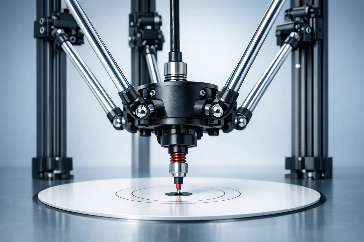
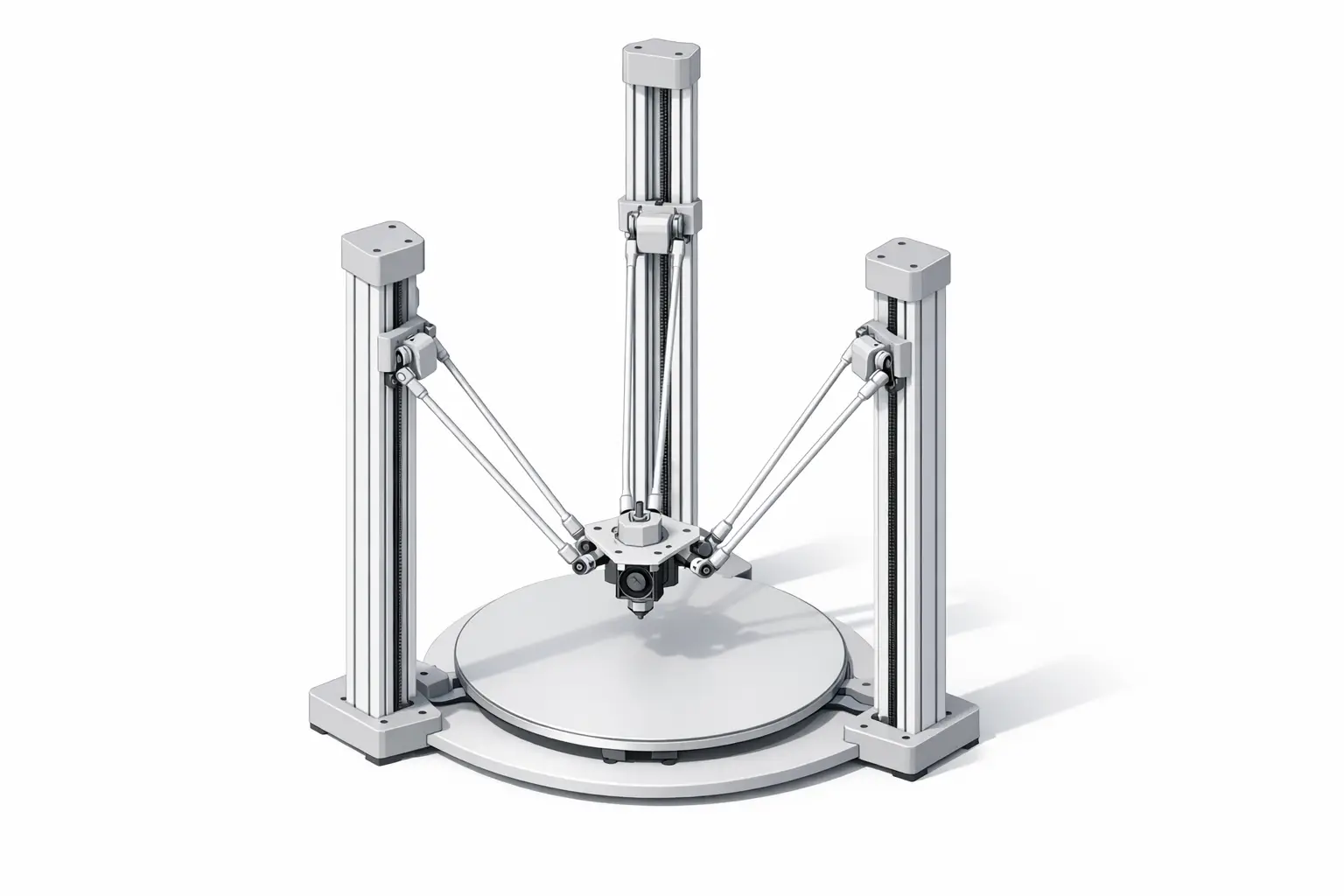
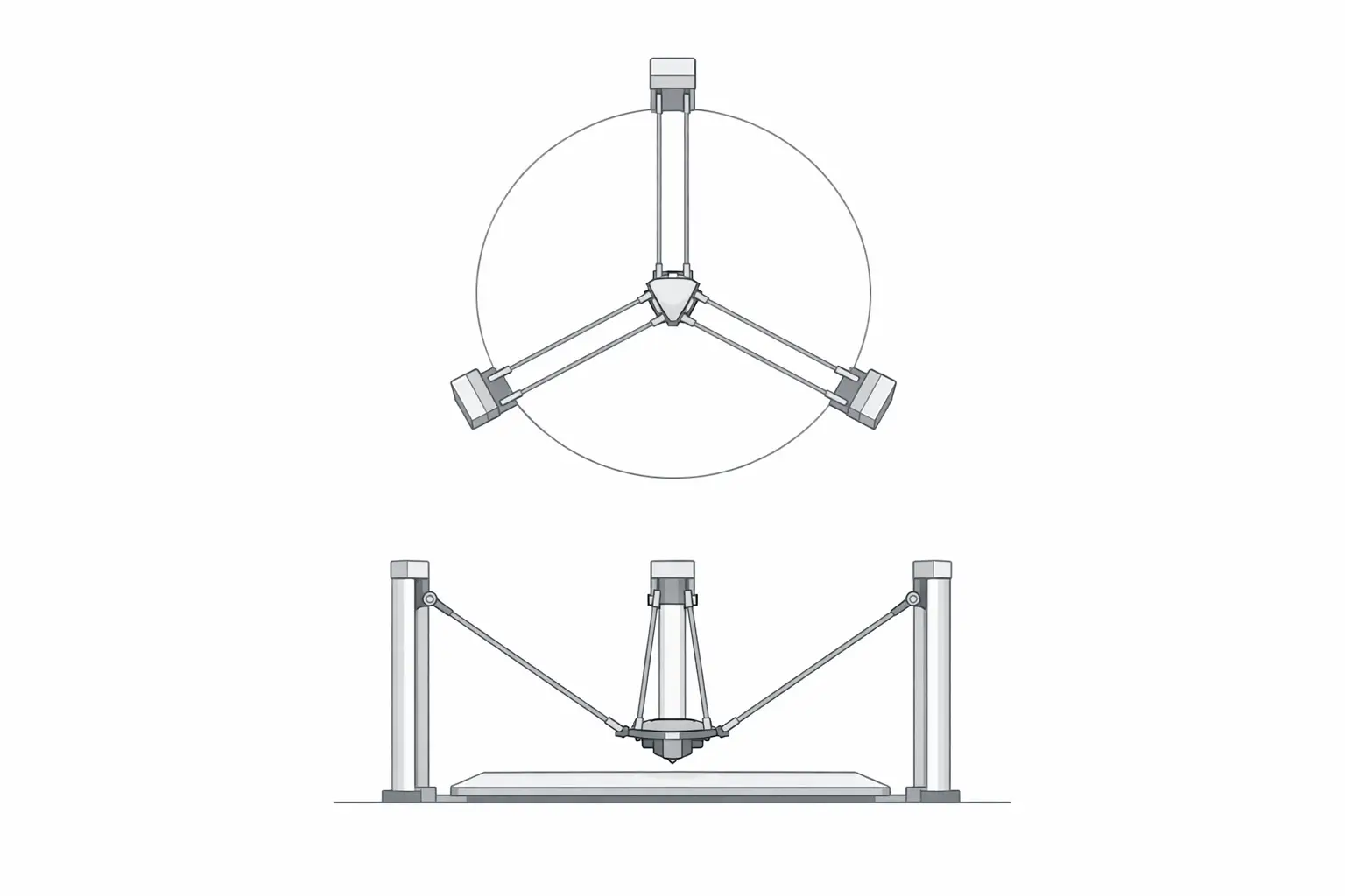
In robotics terminology, a delta mechanism is a parallel robot in which multiple arms constrain an end effector to translational motion through coordinated actuator movement; early U.S. patent lineage for this mechanism is associated with Reymond Clavel, with a cited prior art date of 1985-12-16 and a granted U.S. patent date of 1990-12-11. [1][2] Peer-reviewed modeling work also appears in the robotics literature (Robotica, Volume 8 Issue 2, April 1990, pp. 105–109; DOI 10.1017/S0263574700007669). [3] In 3D printing, a “delta 3D printer” typically refers to a linear delta printer: three vertical towers arranged around a central build area, each with a moving carriage connected by diagonal rods (arms) to a central effector that carries the hotend or toolhead. A commonly referenced layout uses approximately 120° spacing between towers. [6]
Within hobbyist and commercial FFF implementations, delta kinematics describes the mathematical mapping between a requested tool position (X/Y/Z) and the three actuator (tower) positions needed to realize it. The mapping is sensitive to small geometric errors because the mechanism’s effective lever arms vary with position, particularly as the effector approaches the edge of the printable radius. Documentation for delta designs and firmware typically emphasizes tower geometry (including 120° “normal” tower angles) and the distinction between nominal geometry and corrected geometry introduced by calibration. [6]
- Core parts and terms
- Tower: One of the vertical structures that guides a linear actuator stage. [6]
- Carriage: The moving stage on a tower that anchors the diagonal rod ends. [5]
- Diagonal rod/arm: The link between a carriage and the effector; also called a delta arm. [8]
- Effector: The end effector platform that carries the toolhead and connects to the arms. [5]
- Delta radius: A geometry parameter used in firmware to relate tower spacing to effector position. [8]
- Printable radius: The usable radial workspace implied by the machine’s geometry and limits. [11]
- Endstop offset: Per-tower homing adjustment used to align the virtual plane after homing. [9]
- Segments per second: A motion-planning setting used to approximate curves/lines in delta motion planning. [8]
Historical Background (from industrial delta robots to hobbyist delta printers)
The delta mechanism is commonly traced to industrial robotics, where it was developed for high-speed handling tasks using a parallel kinematic structure. U.S. patent US4976582A lists a prior art date of 1985-12-16, which is often used as a reference point for the mid-1980s patent lineage of the delta robot concept; this date should be distinguished from the later grant date. [1] A corresponding U.S. patent record (U.S. Patent 4,976,582) lists the date of patent as 1990-12-11 and identifies Reymond Clavel as inventor. [2] In parallel, academic treatment of delta robot modeling appears in the early 1990s robotics literature, including a Robotica article (Volume 8 Issue 2, April 1990, pp. 105–109; DOI 10.1017/S0263574700007669) that is frequently cited as an early formal reference for delta robot kinematics and mechanism description. [3]
Industrial use emphasizes dynamics and throughput rather than geometric static accuracy alone. ABB’s IRB 365 delta robot, for example, is specified with a payload of 1.5 kg and includes a throughput example of 120 picks per minute for 1 kg products, illustrating why delta architectures are associated with high-speed pick-and-place in packaging and similar applications. [4] Such figures are task- and application-dependent and describe a repetitive manipulation cycle rather than continuous-path motion with deposition constraints. Nevertheless, this industrial context shaped the intuition that parallel mechanisms can deliver high accelerations when the moving mass is kept low and when actuators can remain relatively stationary.
Adoption in 3D printing is strongly associated with RepRap-era experimentation, where builders adapted “linear delta” layouts to filament extrusion. The RepRap Rostock project page documents a delta printer built in 2012 in Seattle, USA, and describes design goals including a build volume of 200 × 200 × 400 mm, positioning speed up to 800 mm/s, a footprint goal of 300 × 350 mm, and an end effector mass target of less than 50 g. [5] These goals summarize the appeal of the delta robot 3D printer configuration in hobbyist terms: a fixed print surface, low moving mass, and the possibility of high positioning speed, with the tradeoff that kinematics and calibration become central engineering concerns rather than minor configuration details. [5]
Mechanical Architecture (Linear Delta) — How Motion Is Produced
A linear delta printer uses three vertical actuators (typically belt-driven or screw-driven stages riding on linear guides) to move three carriages up and down the towers; each carriage is connected to the effector via diagonal rods that form a set of parallel linkages. Coordinated carriage motion constrains the effector to translations in X, Y, and Z over the build area, while the print surface is often stationary during printing. RepRap Rostock documentation explicitly frames “the print surface never moves” as a design goal and also documents an end effector mass target of less than 50 g, reflecting a common delta architecture objective: keep the moving toolhead assembly light so that dynamic motion (especially travel moves and direction changes) does not require accelerating a large heated bed or gantry. [5] The same mechanical premise can be implemented with different extruder configurations and toolhead arrangements, but the defining feature is the parallel robot constraint of the effector via three tower-driven linkages. [3]
Delta Kinematics and Motion Planning (Delta Kinematics)
Delta kinematics is usually discussed in terms of inverse kinematics: given a desired tool position (X/Y/Z), the controller computes the three carriage heights needed to place the effector at that point. Firmware therefore maintains a geometric model that includes arm length and an effective radius term, and it applies additional corrections to account for tower angle deviations and homing offsets. In Marlin, the M665 Delta Configuration command enumerates geometry-related parameters such as H (Delta height), L (diagonal rod), R (delta radius), and S (segments per second), and also includes angle trims for tower alignment. [8] Klipper similarly describes delta calibration in terms of identifying tower endstop positions, tower angles, delta radius, and delta arm lengths, reflecting broadly similar parameterization across firmware ecosystems even when variable names differ. [10] RepRap-oriented documentation also discusses “normal 120°” tower angles and notes that nonstandard arrangements can reduce usable workspace, which is one reason tower-angle error is treated as a calibratable term rather than an ignorable construction detail. [6]
Because multiple parameters can produce similar observable errors (e.g., a wrong delta radius can resemble a tower-angle or endstop-offset problem over limited probing regions), calibration is often posed as a least-squares fitting problem over many measured points. Escher3D’s delta calibration wizard describes least-squares delta calibration factor sets of 3, 4, 6, or 7 factors, including endstops, delta radius, tower angular corrections, and diagonal rod length. [11] The existence of multiple “factor counts” reflects practical identifiability: solving more parameters may improve flatness only if the measurement data supports separating coupled effects. Motion planning also interacts with the kinematic model: Marlin’s M665 includes an S parameter (segments per second) used to control segmented linearization, a technique in which nominal straight or curved paths are approximated by short segments so that the non-linear delta transform can be applied accurately and efficiently during planning. [8]
- Parameters commonly solved during calibration
- Endstop offsets: Per-tower adjustments that compensate homing differences. [9]
- Delta radius: A geometry term that influences the curvature of the implied bed plane and edge behavior. [8]
- Diagonal rod length: The effective arm length used in the kinematic model. [8]
- Tower angular corrections: Adjustments for tower-angle deviations from the nominal layout. [8]
- Homed height/delta height: The Z reference (height) used after homing. [7]
Calibration and Tuning Workflow (Marlin, Klipper, RepRapFirmware)
Delta printer calibration is commonly organized as an iterative loop: home the machine to establish a repeatable reference, collect measurements over the build area (typically with a Z probe), fit a geometric model, and validate by re-measuring and printing test artifacts. In Marlin, G33 Delta Auto Calibration is explicitly described as calibrating Delta Height, endstops, Delta Radius, and Tower Angles, which corresponds to the main terms that dominate “bed level” behavior in a delta’s kinematic model. [7] After a solution is found, parameters are stored or applied through configuration commands: Marlin’s M665 lists delta geometry and planning-related parameters (including H, L, R, S, and angle trims), while M666 is used to adjust delta endstop offsets for the X/Y/Z actuators. [8][9]
Calibration quality is bounded by the repeatability of homing and probing, because the solver can only fit a model to the measurements it is given. Klipper’s delta calibration documentation emphasizes identifying tower endstop positions and other geometry terms, implying that endstop behavior is a foundational assumption for the rest of the model. [10] In practical terms, if endstop offsets drift or the probe produces inconsistent trigger heights, the same least-squares method that can reduce systematic geometric error may instead fit noise, and the resulting “solution” can be unstable across time or temperature. [11]
Different firmware ecosystems converge on similar ideas while varying in workflow and naming. Klipper describes calibration as identifying tower endstop positions, tower angles, delta radius, and delta arm lengths, aligning with the conceptual parameter list used in Marlin’s M665 and with least-squares “factor sets” described by Escher3D. [10][8][11] Escher3D’s statement that least-squares calibration supports 3, 4, 6, or 7 factors provides a concise framework for describing tuning strategies without prescribing a single correct procedure: fewer factors can be more robust when measurements are limited, while more factors may be necessary when the mechanism includes measurable tower-angle or rod-length deviations. [11]
Performance Characteristics (Fast 3D Printing) — What “Speed” Means
In delta 3D printer marketing and documentation, “speed” can refer to at least three different quantities: maximum print speed (deposition moves under extrusion), maximum travel speed (non-printing moves), and maximum acceleration (rate of speed change), and manufacturers may publish different combinations. The manufacturer of the Delta WASP 2040 PRO states a maximum print speed of 500 mm/s, a maximum travel speed of 800 mm/s, and a maximum acceleration of 15,000 mm/s², illustrating how print, travel, and acceleration are separated as distinct metrics. [12] SeeMeCNC’s RostockMAX v4 distinguishes maximum printing speed as 100 mm/s (at 0.2 mm layer height) and maximum travel speed as 350 mm/s, reflecting a more conservative presentation tied to a stated print condition. [13] FLSUN’s V400 Max product page states a print speed of 600 mm/s, while RepRap Rostock documentation lists a positioning speed goal up to 800 mm/s, showing that both commercial listings and project documentation may foreground high-speed motion as a key delta kinematics benefit even when real print throughput also depends on extrusion limits and quality constraints. [14][5]
Build Volume Geometry and Usable Area (Cylindrical Envelope)
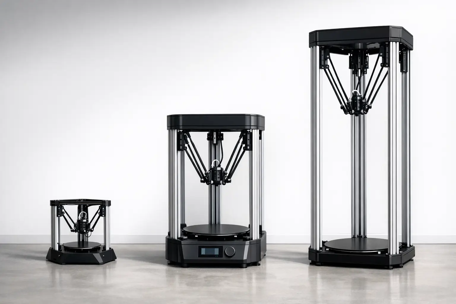
Many delta printers describe build volume as a cylinder because the reachable workspace of the effector is often bounded by radial limits: as the effector approaches the towers, the arm geometry and carriage travel limits reduce reachable positions, producing an approximately circular printable area in X/Y and a separate Z height limit. This is reflected in vendor specifications that use diameter-by-height notation, such as the Delta WASP 2040 PRO build volume stated as Ø 200 × h 400 mm and the SeeMeCNC RostockMAX v4 print area stated as 280 mm Dia × 385 mm H. [12][13]
A cylindrical envelope has practical implications for part layout and slicing. Rectangular parts can be placed within a circular boundary, but corners near the maximum printable radius may approach regions where calibration error and kinematic sensitivity have a larger effect on first-layer flatness, particularly if the model includes imperfect tower angles or an incorrect delta radius. Firmware calibration therefore often aims to make the implied bed plane consistent across the usable radius, not only at the center. Marlin’s G33 explicitly targets terms (including delta radius and tower angles) that affect this center-versus-edge behavior, while geometry parameters in M665 define the model used to transform toolpaths into actuator motion. [7][8]
Representative Delta Printer Specifications (Commercial Examples)
Published specifications for delta printers are often not directly comparable because vendors report different maxima, different test conditions, and different definitions of “precision,” “speed,” or “resolution.” For example, one product page may list a maximum travel speed and acceleration (which primarily describe motion capability), while another lists a maximum recommended printing speed tied to a particular layer height. A neutral comparison therefore treats these values as vendor-stated and focuses on what is explicitly claimed rather than inferring real-world throughput across materials and geometries. [12][13]
The examples below illustrate three common positions in the market: a mid-size professional delta with explicit acceleration and travel metrics (Delta WASP 2040 PRO), a kit-derived commercial delta that reports printing and travel speeds separately and includes a probe deviation metric (SeeMeCNC RostockMAX v4), and a large-format high-speed delta that includes vendor-stated “precision” and high hotend temperature (FLSUN V400 Max). [12][13][14] Where a specification is not listed in the cited source, it is reported as “No reliable figure found” to avoid estimation.
The table groups multiple metrics into single cells to emphasize that the underlying test methodology is typically undocumented on product pages. It should also be read as a snapshot: firmware configuration (e.g., segments per second) and calibration outcomes (e.g., tower-angle correction) can materially affect whether high travel speeds translate into acceptable print quality for a given part. [8]
| Model | Build volume | Motion (vendor-stated) | Thermal / quality (vendor-stated) |
|---|---|---|---|
| Delta WASP 2040 PRO | Ø 200 × h 400 mm. [12] | Max print speed: 500 mm/s. [12] Max travel speed: 800 mm/s. [12] Max acceleration: 15,000 mm/s². [12] |
Standard nozzle: 0.4 mm. [12] Min layer height: 50 micron. [12] Max bed temperature: 110 C°. [12] |
| SeeMeCNC RostockMAX v4 | 280 mm Dia × 385 mm H. [13] | Max printing speed: 100 mm/s (at 0.2 mm layer height). [13] Max travel speed: 350 mm/s. [13] |
Min layer height: 0.08 mm (with 0.5 mm nozzle). [13] Max hotend temperature: 280 C. [13] Max bed temp: 110 C. [13] Step resolution: 0.01 mm. [13] Typical probe deviation: 0.08–0.13 mm. [13] |
| FLSUN V400 Max | Build volume: 500 mm × 550 mm (up to 480 mm height). [14] | Print speed: 600 mm/s. [14] | Precision: ±0.1 mm. [14] Hotend up to 350°C. [14] Heated bed up to 100°C. [14] Power: 220V~1400W. [14] |
Limitations and Failure Modes (Engineering-Focused)
A delta 3D printer’s primary engineering limitation is sensitivity to geometric modeling error: because the mechanism is parallel-kinematic, small errors in parameters such as diagonal rod length, delta radius, and tower angles can manifest as position-dependent Z deviations, particularly toward the edge of the printable radius where the linkage geometry changes most rapidly. Firmware documentation implicitly reflects this by exposing multiple coupled geometry terms (Marlin M665) and by providing an automated solver intended to adjust delta height, endstops, delta radius, and tower angles (Marlin G33). [8][7] Klipper’s calibration documentation similarly frames delta calibration as the identification of tower endstop positions, tower angles, delta radius, and delta arm lengths, emphasizing that accurate motion depends on a consistent model rather than a single “bed leveling” offset. [10] In practice, failure modes often combine mechanical and measurement factors: endstop offsets (Marlin M666) can drift with switch wear or mounting changes; arm joint play and belt tension variation can change effective geometry; and probing noise can cause least-squares methods to converge to different local solutions across sessions. [9][11] Finally, slicing and motion configuration interact with quality: high vendor-stated travel or print speeds do not guarantee high-quality deposition if the chosen motion segmentation and acceleration limits excite ringing, overshoot, or extrusion dynamics that a given hotend and filament system cannot sustain, and these effects are typically outside what a pure kinematic calibration can correct. [8]
Delta vs Cartesian/CoreXY (Comparison Table + Selection Criteria)
Selection criteria for delta versus Cartesian or CoreXY printers often depend on part geometry, tolerance to calibration effort, and physical constraints. Delta printers are frequently chosen for tall parts and for designs where keeping the build surface fixed is desirable, while Cartesian and CoreXY arrangements may be preferred where users prioritize straightforward axis mapping and simpler geometric calibration. Industrial usage of delta robots for high-throughput pick-and-place provides context for why the delta architecture is associated with high dynamics: ABB’s IRB 365 lists a throughput example of 120 picks per minute for 1 kg products. [4] Printer specifications similarly foreground speed metrics, such as a stated maximum acceleration of 15,000 mm/s² for the Delta WASP 2040 PRO or a stated print speed of 600 mm/s for the FLSUN V400 Max, although these values do not directly translate into equivalent print quality or throughput across machines. [12][14]
A qualitative comparison can be more useful than an implied ranking because each architecture trades off mechanical complexity, calibration variables, and enclosure/maintenance constraints. Delta calibration exposes multiple coupled geometry variables (e.g., delta radius and tower angles), whereas Cartesian systems more often treat axis orthogonality and bed plane alignment as separable adjustments. The table below summarizes common considerations at a high level without asserting universal superiority.
| Attribute | Delta (linear delta) | Cartesian | CoreXY |
|---|---|---|---|
| Moving mass distribution | Toolhead/effector is typically the primary moving mass, with towers carrying actuators and carriages. [5] | Often moves a gantry and/or bed depending on design; mass distribution varies by implementation. | Typically moves a gantry with coupled belts; bed motion varies by design. |
| Calibration variables | Multiple coupled geometry terms are commonly calibrated (e.g., delta radius, tower angles, endstop offsets). [7][8][10] | Often focuses on axis steps, orthogonality, and bed plane alignment; fewer coupled kinematic terms are exposed in common firmware. | Similar to Cartesian in toolpath space, with additional belt routing considerations; kinematics is planar but belt coupling can affect squareness. |
| Typical advertised build shape | Often expressed as a cylindrical build volume. [12][13] | Often expressed as a rectangular prism build volume. | Often expressed as a rectangular prism build volume. |
| Speed metrics used | Vendors may list print, travel, and acceleration separately. [12][13] | Vendors may list print speed; travel/acceleration reporting varies by product. | Vendors often emphasize speed; reporting practices vary by product. |
| Maintenance access | Tower components and arms are distributed around the frame; effector access depends on height and frame design. [5] | Access depends on frame and bed arrangement; fewer long arms/joints than delta. | Belt path complexity can increase maintenance points; gantry access depends on enclosure and frame. |
| Enclosure friendliness | Tall frames can be less convenient to enclose; suitability depends on the specific machine geometry and height. [12][13] | Enclosures are common, particularly for box-frame designs; suitability depends on bed motion and footprint. | Enclosures are common for cube frames; suitability depends on footprint and intended materials. |
Standards, Terminology, and Further Reading
Key terms are used inconsistently across firmware and vendor pages, so definitions are often best anchored to the parameter names used in major firmware documentation. In Marlin, delta radius and diagonal rod length appear explicitly in M665, while endstop offsets are adjusted with M666 and an automated approach is documented under G33. [8][9][7] Klipper’s delta calibration documentation uses closely related terms (tower endstop positions, tower angles, delta radius, delta arm lengths), which can help readers translate between firmware ecosystems. [10]
Several ambiguous metrics benefit from careful reading. “Accuracy” and “precision” are sometimes used interchangeably in product listings, but a vendor-stated “precision” metric (such as ±0.1 mm on the FLSUN V400 Max page) should be treated as a claim unless accompanied by a defined test method. [14] “Print speed” versus “travel speed” similarly requires context: one product page may state both, while another reports only a maximum printing speed under a particular layer-height condition. [12][13]
Further reading that covers the mechanism, modeling context, firmware parameterization, and representative specifications includes the delta robot patent record (US4976582A and U.S. Patent 4,976,582), early robotics literature (Robotica, April 1990), firmware documentation (Marlin and Klipper), and manufacturer specification pages used for example comparisons (Delta WASP, SeeMeCNC, FLSUN). [1][2][3][7][8][10][12][13][14]
Q&A (FAQ)
1) What is a delta 3D printer (delta kinematics) and how does it differ from Cartesian motion?
A delta 3D printer is a parallel-kinematic arrangement derived from the delta robot mechanism, where multiple actuators move in coordination to position an end effector, rather than mapping X, Y, and Z to separate orthogonal linear axes. The mechanism’s patent lineage is commonly associated with Reymond Clavel, with a cited prior art date of 1985-12-16 for US4976582A and a U.S. patent date of 1990-12-11 for U.S. Patent 4,976,582. [1][2] Early robotics modeling literature (Robotica, Volume 8 Issue 2, April 1990, pp. 105–109; DOI 10.1017/S0263574700007669) provides a formal kinematic and mechanism context that later informed how “delta kinematics” is discussed in 3D printer firmware. [3]
2) Which parameters matter most in delta printer calibration (delta radius, diagonal rod length, tower angles)?
Delta printer calibration typically focuses on parameters that define the kinematic model and the homed reference. Marlin’s M665 identifies core geometry terms such as delta height (H), diagonal rod length (L), and delta radius (R), along with angle trims, while Marlin’s G33 describes an automated calibration that can calibrate Delta Height, endstops, Delta Radius, and Tower Angles. [8][7] Klipper’s delta calibration similarly describes identifying tower endstop positions, tower angles, delta radius, and delta arm lengths. [10] Least-squares tools such as Escher3D’s delta calibration wizard describe solving different factor sets (3, 4, 6, or 7 factors) that include endstops, delta radius, tower angular corrections, diagonal rod length, reflecting which parameters can be identified given the available measurements. [11]
3) How fast can a delta 3D printer print (fast 3D printing) — and what do manufacturers mean by “speed”?
Manufacturers may mean maximum printing speed (under extrusion), maximum travel speed (non-extrusion motion), or maximum acceleration (how quickly the system changes speed). The Delta WASP 2040 PRO product page states a maximum print speed of 500 mm/s, a maximum travel speed of 800 mm/s, and a maximum acceleration of 15,000 mm/s², separating these categories explicitly. [12] SeeMeCNC’s RostockMAX v4 page states a maximum printing speed of 100 mm/s (at 0.2 mm layer height) and a maximum travel speed of 350 mm/s, illustrating a condition-based printing-speed figure. [13] The FLSUN V400 Max page states a print speed of 600 mm/s, which should be read as a vendor claim rather than a universal throughput guarantee across parts and materials. [14]
4) Why are many delta printers specified with a cylindrical build volume (e.g., Ø200 × h400)?
A cylindrical build volume is a convenient way to describe a delta’s reachable X/Y workspace, which is often bounded by radial constraints from tower placement, arm geometry, and carriage travel, combined with an independent Z height limit. The Delta WASP 2040 PRO lists its build volume as Ø 200 × h 400 mm, and the SeeMeCNC RostockMAX v4 lists a print area of 280 mm Dia × 385 mm H, both using a diameter-by-height format consistent with a cylinder. [12][13] Practically, this means that rectangular parts must fit within a circle in plan view, and that layouts near the maximum radius may be more sensitive to calibration and geometric error than parts near the center.
5) Expert — How does least-squares calibration reduce delta bed-height error, and which parameters are identifiable?
Least-squares calibration reduces systematic error by fitting a kinematic model to many measured points rather than adjusting one parameter at a time. Escher3D’s delta calibration wizard describes least-squares calibration factor sets of 3, 4, 6, or 7 factors, including endstops, delta radius, tower angular corrections, and diagonal rod length, which reflects that not all parameters are equally identifiable from limited probing data and that some parameters are coupled. [11] Firmware features such as Marlin’s G33 (which targets delta height, endstops, delta radius, and tower angles) and geometry parameters in Marlin’s M665 provide the named variables that such solvers adjust in practice. [7][8]
6) Expert — How do industrial delta robots relate to delta 3D printers, and why should readers not directly compare “picks/min” to “mm/s”?
Industrial delta robots and delta 3D printers share a parallel-kinematic concept, but their performance metrics measure different tasks. ABB’s IRB 365 lists a throughput example of 120 picks per minute for 1 kg products, which describes a repetitive pick-and-place cycle under defined conditions rather than continuous-path deposition. [4] By contrast, 3D printer metrics such as a stated maximum print speed (e.g., 500 mm/s for the Delta WASP 2040 PRO or 600 mm/s for the FLSUN V400 Max) describe axis motion limits in a context where extrusion flow, layer adhesion, and surface quality constrain usable throughput. [12][14] For this reason, industrial “picks/min” and printer “mm/s” should be interpreted within their respective task models rather than compared as interchangeable measures of system capability.
Sources
- US4976582A — patents.google.com
- US Patent 4,976,582 — patents.justia.com
- “Delta: A simple and efficient parallel robot” (Robotica, 1990) — Cambridge PDF
- ABB IRB 365 Delta Robot — product page
- RepRap Rostock — project wiki
- RepRap Delta-Pi — tower angle discussion
- Marlin G33 — Delta Auto Calibration
- Marlin M665 — Delta Configuration
- Marlin M666 — Set Delta Endstop Adjustments
- Klipper — Delta Calibrate
- Escher3D — Least-squares Delta Calibration Wizard
- Delta WASP 2040 PRO — manufacturer specifications
- SeeMeCNC RostockMAX v4 — manufacturer specifications
- FLSUN V400 Max — manufacturer specifications