Summary (direct answer)
In standards-based terminology, additive manufacturing (AM) is the “process of joining materials to make parts from 3D model data, usually layer upon layer…”, and an AM system is the “machine and auxiliary equipment used for additive manufacturing.” [1] In practice, an industrial 3D printer is therefore a factory-oriented AM system emphasizing controlled materials, repeatability, throughput, monitoring, and facility readiness across the seven process categories: Binder Jetting, Directed Energy Deposition, Material Extrusion, Material Jetting, Powder Bed Fusion, Sheet Lamination, and Vat Photopolymerization. [2]
Definition and scope — “industrial” vs “professional” vs “consumer”
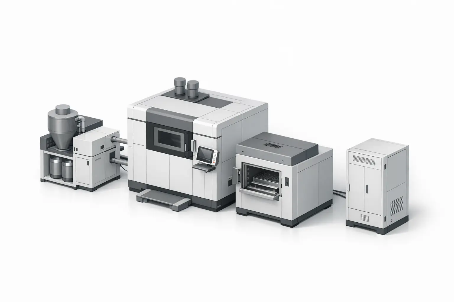
“Industrial 3D printer” is commonly used to describe an additive manufacturing system rather than only a standalone printer, because production deployments depend on auxiliary equipment (e.g., powder handling, drying, in-process monitoring, and post-processing) and on defined operating constraints. [1] This scope also aligns with factory documentation practices, where vendor specifications often include environmental limits, utilities, and connected-workflow capabilities in addition to geometric performance.
In industrial installations, facility requirements can be decisive. For example, Stratasys documents power requirements of 230 VAC (three phase) 50/60 Hz at 40 A and compressed air of 90–120 psi with minimum flow 20 CFM for the F900 AM machine, alongside installation-relevant system size (2,772 × 1,683 × 2,027 mm) and weight (2,869 kg). [9] Such requirements tend to be less prominent in “professional” or “consumer” categories, which are often described primarily by build volume, layer thickness, and user features.
Historical background (key inventions and industrialization milestones)
Several industrial 3D printing technologies trace to distinct invention lineages documented in patent records and institutional histories. Stereolithography (SLA) is associated with U.S. Patent 4,575,330 (Date of Patent: Mar 11, 1986), inventor Charles W. Hull, establishing vat photopolymerization as an early production-capable AM approach. [5] Polymer powder-bed fusion development is represented by U.S. Patent 4,863,538 (Filed: Oct 17, 1986; Date of Patent: Sep 5, 1989), inventor Carl R. Deckard, a lineage that later expanded into industrial laser-sintering platforms. [7] Binder jetting is represented by U.S. Patent 5,204,055 (Filed: Dec 8, 1989; Date of Patent: Apr 20, 1993), with inventors including Emanuel M. Sachs; MIT News describes the method as an inkjet binder selectively deposited into a powder bed, layer by layer, and notes Sachs’ role in the invention narrative. [8][10] Material extrusion’s industrialization is linked to U.S. Patent 5,121,329 (Date of Patent: Jun 9, 1992), inventor S. Scott Crump, assignee Stratasys, Inc., filed Oct 30, 1989, a foundation for factory-grade fused deposition modeling and related implementations. [6] For directed energy deposition (DED), Sandia National Laboratories describes LENS technology as “initiated at Sandia in 1995,” reflecting a repair and near-net-shape metal deposition context that differs operationally from powder-bed systems. [11]
Technology taxonomy (process categories used in industrial printers)
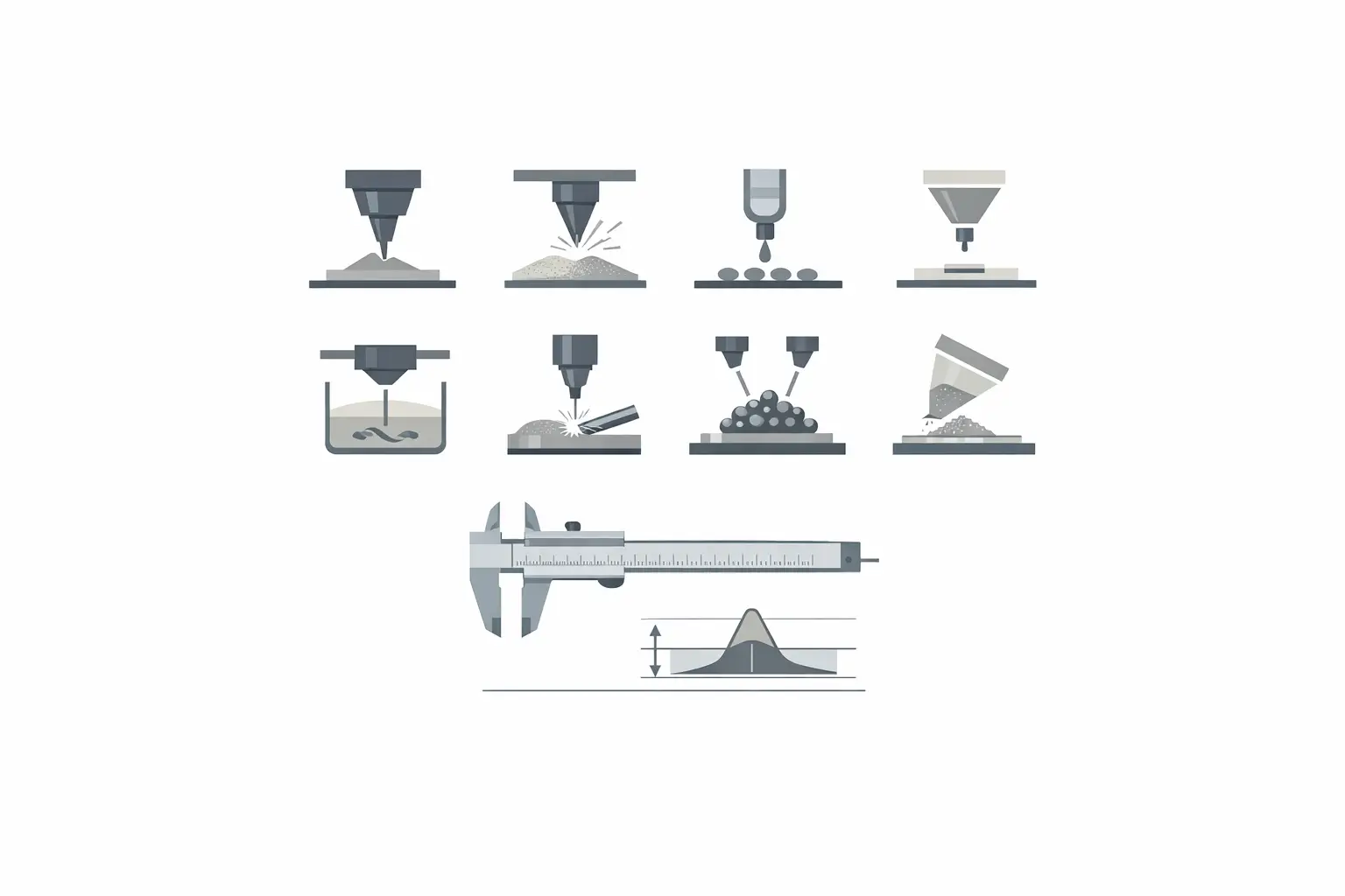
A common cross-vendor way to classify industrial additive manufacturing is by process category rather than by product branding. HP presents a seven-category taxonomy: Binder Jetting, Directed Energy Deposition, Material Extrusion, Material Jetting, Powder Bed Fusion, Sheet Lamination, and Vat Photopolymerization. [2] In industrial documentation, branded terms (e.g., “DMLS-family” naming under metal powder-bed fusion) are often mapped to these categories for comparability, while acknowledging that parameter sets, materials, and qualification methods differ between implementations.
Government sources may describe a subset of categories for research and measurement framing. NIST lists and describes Powder Bed Fusion, Directed Energy Deposition, Material Extrusion, Vat Photopolymerization, Binder Jetting, and Material Jetting, and the page indicates “Updated April 15, 2025.” [3] This list is descriptive but does not present the full seven-category set (e.g., Sheet Lamination is not included on that page), so industrial comparisons typically use the broader taxonomy as a top-level grouping and then apply process-specific metrics and post-processing considerations. [3][2]
- Binder Jetting [2]
- Directed Energy Deposition [2]
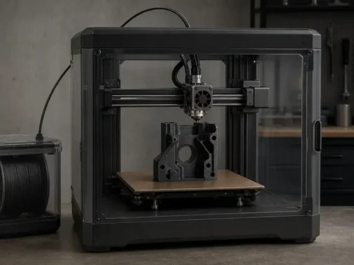
- Material Extrusion [2]
- Material Jetting [2]
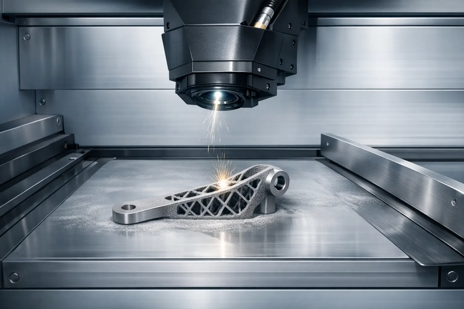
- Powder Bed Fusion [2]
- Sheet Lamination [2]
- Vat Photopolymerization [2]
Technical performance metrics (what manufacturers publish — and what they omit)
Industrial additive manufacturing specifications typically combine geometry, process parameters, and production-operational constraints, but they do not standardize meaning across technologies. Build envelope/build volume indicates the maximum part space but not the usable space after supports, recoaters, or “printable” region conventions, which vary by vendor. For achievable accuracy, Stratasys defines F900 “Achievable Accuracy” as ±0.089 mm or ±0.0015 mm per mm (whichever is greater), with Z including an additional tolerance of -0.000/+ slice height, and states it is “derived from statistical data at 95% dimensional yield,” illustrating that published accuracy is conditional on geometry, process control, and definition method. [9] Metal powder bed fusion specifications may emphasize energy delivery and scanning parameters; EOS lists a scan speed up to 7.0 m/s and a focus diameter of approx. 100 µm for the EOS M 290, which are not direct proxies for part throughput because throughput also depends on layer thickness, hatch strategy, packing density, and post-processing (e.g., depowdering and heat treatment). [12] Vendors may publish cycle-time figures as mode-based print times; HP lists print time of 12 hrs (Balanced print mode), 9.40 hrs (Fast print mode), and 13.50 hrs (Robust print mode) for HP Jet Fusion 5200 Series, but such figures may not include cooling, unpacking, or downstream finishing. [13] Photopolymer platforms may separate resolution from dimensional performance; Carbon lists XY and Z resolution values on the M3 page (XY 160 µm; Z 25, 50, or 100 µm) while separately expressing “General Accuracy (M2)” as up to ±70 μm + 1 μm per mm dimension size and “Production Repeatability Accuracy” up to ±40 μm, underscoring that “resolution,” “accuracy,” and “repeatability” are distinct metrics with different test dependencies. [15][16]
Representative systems and comparison table (vendor-published specs)
The systems below are representative in the narrow sense that each is a documented industrial AM machine within a defined process category, with vendor-published specifications suitable for illustrating how industrial documentation differs across technologies. The comparison is not a ranking, and it avoids normalizing performance into a single cross-process metric, because published figures (e.g., scan speed, achievable accuracy, or print time modes) are not directly comparable without shared test artifacts and production assumptions. [9][12]
Where a process category is listed without a representative machine in the provided fact set, the entry is marked “No reliable figure found” to avoid substituting unsourced models or numeric thresholds. [2]
Representative Industrial 3D Printers by Process Category (Vendor-Published Specs)
| Process category (ISO/ASTM) | Example system (model) | Build volume / build envelope (with units) | Vendor-published metric(s), facility requirements, and notes |
|---|---|---|---|
| Binder Jetting | No reliable figure found | No reliable figure found | Performance metric: No reliable figure found. Facility requirements: No reliable figure found. Notes: Vendor “print speed” claims are often process- and material-dependent; no vendor-published spec is provided here. |
| Directed Energy Deposition | No reliable figure found | No reliable figure found | Performance metric: No reliable figure found. Facility requirements: No reliable figure found. Notes: DED is often specified by deposition head and energy source parameters; no representative industrial datasheet is provided here. |
| Material Extrusion | Stratasys F900 | 914.4 × 609.6 × 914.4 mm (36 × 24 × 36 in.). [9] | Performance metric: Achievable Accuracy ±0.089 mm or ±0.0015 mm per mm (whichever is greater); Z includes additional tolerance of -0.000/+ slice height; derived from statistical data at 95% dimensional yield. [9] Facility requirements: 230 VAC (three phase) 50/60 Hz; current 40 A; compressed air 90–120 psi; minimum flow 20 CFM. [9] Notes: “Achievable accuracy” is a vendor-defined statistical statement and is not equivalent to nozzle diameter or layer thickness. [9] |
| Material Extrusion | BigRep ONE | x 1005 y 1005 z 1005 (mm). [14] | Performance metric: Layer height resolution 0.1 mm – 1.4 mm. [14] Facility requirements: Print bed temperature max. 80 °C; printer weight approx. 460 kg. [14] Notes: Large build volume does not imply fine detail; layer height range indicates a wide process window that trades surface finish for throughput. [14] |
| Material Jetting | No reliable figure found | No reliable figure found | Performance metric: No reliable figure found. Facility requirements: No reliable figure found. Notes: Industrial material jetting is commonly specified by droplet/pixel parameters and post-curing steps; no representative industrial datasheet is provided here. |
| Powder Bed Fusion | EOS M 290 | 250 × 250 × 325 mm. [12] | Performance metric: Laser power 1 × 400 W (Yb-fiber laser); scan speed up to 7.0 m/s; focus diameter approx. 100 µm. [12] Facility requirements: No reliable figure found. Notes: Scan speed and focus diameter are process parameters and do not alone predict part cycle time or final tolerances. [12] |
| Powder Bed Fusion | HP Jet Fusion 5200 Series | Effective build volume 380 × 284 × 380 mm (15 × 11.2 × 15 in). [13] | Performance metric: Print time 12 hrs (Balanced print mode); 9.40 hrs (Fast print mode); 13.50 hrs (Robust print mode). [13] Facility requirements: No reliable figure found. Notes: Mode-based “print time” figures may exclude cooling and post-processing, and are not directly comparable to laser scan speeds. [13] |
| Sheet Lamination | No reliable figure found | No reliable figure found | Performance metric: No reliable figure found. Facility requirements: No reliable figure found. Notes: Sheet lamination systems are often constrained by bonding method and sheet handling; no representative industrial datasheet is provided here. |
| Vat Photopolymerization | Carbon M3 Max | 400 × 250 × 460 mm (15.7 × 9.8 × 18.1 in). [15] | Performance metric: XY; Z Resolution 160 µm; 25, 50, or 100 µm. [15] Facility requirements: No reliable figure found. Notes: Resolution is not the same as dimensional accuracy or production repeatability, which may be specified separately by model family. [15][16] |
| Vat Photopolymerization | 3D Systems Figure 4 Production | Printable build volume (W × D × H) 124.8 × 70.2 × 346 mm (4.9 × 2.8 × 13.6 in). [17] | Performance metric: No reliable figure found. Facility requirements: No reliable figure found. Notes: “Printable” volume wording may reflect a constrained region defined by optics, material handling, or process controls rather than a simple chamber size. [17] |
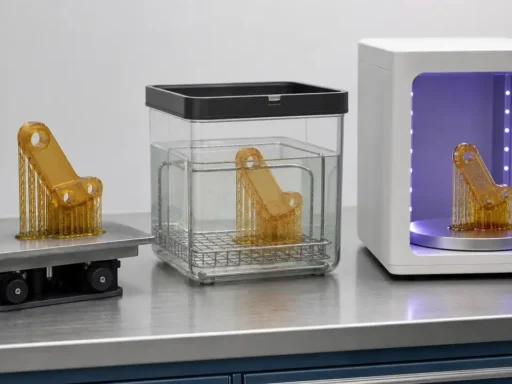
Factory workflow and integration (pre — print — post)
Industrial AM workflows typically separate pre-processing (data preparation, build setup, nesting, parameter selection), printing (job execution with monitoring and traceability), and post-processing (support removal, depowdering, curing, heat treatment, and inspection) in ways that vary strongly by process category. NIST’s technology descriptions emphasize these process differences at a high level (e.g., the powder-handling and fusion steps in powder bed fusion versus material delivery and solidification in extrusion or vat photopolymerization). [3] Vendor documentation also highlights factory integration claims, but the scope is implementation-dependent: EOS describes “EOS System Suite” as integrating with manufacturing execution system (MES) and shop-floor IT systems and generating detailed quality reports, while Stratasys references MTConnect readiness for connected-factory workflows and also describes data security including U.S. Department of Defense STIG compliance via ProtectAM technology. [12][9]
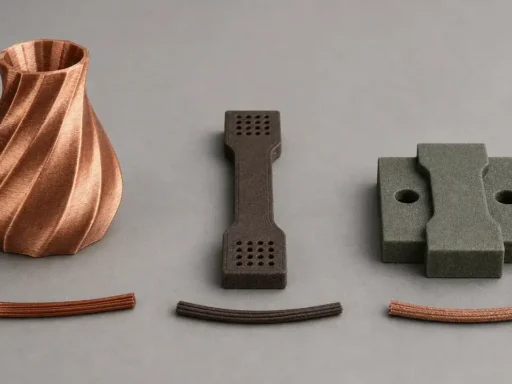
Applications in industry (where each process is typically used)
Industrial polymer systems are commonly selected when geometric complexity, weight reduction, corrosion resistance, or electrical insulation are required, but the attainable surface finish, anisotropy, and post-processing burden differ by process family. NIST descriptions distinguish, for example, material extrusion’s filament or feedstock deposition behavior from vat photopolymerization’s liquid resin curing behavior and powder bed fusion’s powder-layer consolidation, which in turn affects support strategies, surface texture, and finishing operations. [3]
Industrial metal systems are typically framed around powder bed fusion and directed energy deposition, with different trade-offs in feature resolution, deposition strategy, and downstream qualification. NIST’s descriptions emphasize that these technologies involve different ways of supplying and consolidating metal (powder-bed layering and energy scanning versus directed deposition with an energy source), and those differences propagate into inspection planning, heat treatment, and part removal steps. [3]
Selection criteria checklist (engineering and operations)
Industrial 3D printer selection is usually constrained as much by operational readiness as by nominal geometric capability. For example, mode-based cycle-time figures (as published for HP Jet Fusion 5200 Series) can be relevant to scheduling, while facility utilities and data-security claims (as published for Stratasys F900) can determine whether a site can install and govern an AM machine within factory policies. [13][9]
- Identify part functional requirements (loads, temperature exposure, chemical environment) and map them to feasible AM process categories. [3]
- Confirm whether the needed material set is compatible with the selected AM machine and its documented workflow. [1]
- Define tolerance and verification approach, and treat vendor “achievable accuracy” as definition-bound rather than universal. [9]
- Compare build envelope/build volume to part size, support strategy, and orientation constraints. [9]
- Evaluate throughput assumptions using vendor-published cycle-time conventions (e.g., mode-based print time) and account for post-processing labor. [13]
- Validate facility readiness (power, compressed air, floor loading, environmental limits) using vendor installation requirements where available. [9]
- Determine integration needs for scheduling and traceability (e.g., MES integration, shop-floor IT connectivity, MTConnect), noting that interfaces may require additional software and validation. [12][9]
- Define cybersecurity and export/control constraints, including any vendor-published STIG-related claims where applicable. [9]
- Plan for quality documentation and reporting expectations, including any vendor tools positioned for quality reports. [12]
Safety, compliance, and environmental requirements
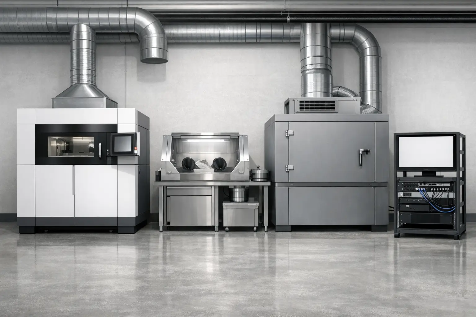
Industrial AM deployments typically require controls addressing electrical power, thermal hazards, airborne particulates and volatile compounds (process- and material-dependent), and safe handling of powders, resins, or heated polymers. Because industrial printers are installed as AM systems, safety considerations often include not only the print engine but also ancillary equipment and post-processing steps (e.g., depowdering stations, curing units, and material storage practices). [1]
Vendors may publish explicit environmental limits as part of installation and operation guidance. For Stratasys F900, maximum room temperature is 29 °C (85 °F) and maximum room humidity is 80%, which are site constraints rather than part-performance metrics. [9] Some industrial spec sheets also include regulatory or conformity references as a documented line item (e.g., Stratasys Fortus 450mc documentation includes a “Regulatory compliance” entry), but the specific certifications and their applicability vary by model configuration and jurisdiction. [18]
Future trends and standardization (bounded, source-driven)
Standardization efforts in industrial additive manufacturing often emphasize shared vocabulary, interoperability, and measurement methods, because cross-process comparisons depend on consistent definitions of terms such as process category and AM system scope. [1] NIST frames AM in definition- and measurement-oriented terms in its public materials, reinforcing the role of process descriptions and metrology in qualifying industrial additive manufacturing. [4]
Q&A (FAQ)
What is an industrial 3D printer (factory-grade 3D) in additive manufacturing terms?
In standards-based terms, AM is the “process of joining materials to make parts from 3D model data, usually layer upon layer…”, and an AM system is the “machine and auxiliary equipment used for additive manufacturing.” [1] “Industrial 3D printer” is typically used to mean a production-deployed AM system, including peripherals and controlled workflows, rather than only the print engine.
What are the seven industrial additive manufacturing process categories (and which ones are most common in factories)?
The seven categories are: Binder Jetting; Directed Energy Deposition; Material Extrusion; Material Jetting; Powder Bed Fusion; Sheet Lamination; Vat Photopolymerization. [2] NIST describes a commonly referenced subset (Powder Bed Fusion; Directed Energy Deposition; Material Extrusion; Vat Photopolymerization; Binder Jetting; Material Jetting) and does not present a full seven-category list on that page. [3]
How do build volume and achievable accuracy differ across industrial 3D printers?
Build envelope/build volume describes maximum geometric capacity, such as the Stratasys F900 build envelope of 914.4 × 609.6 × 914.4 mm. [9] Achievable accuracy is a separate, definition-bound performance statement; Stratasys specifies F900 achievable accuracy as ±0.089 mm or ±0.0015 mm per mm (whichever is greater), derived from statistical data at 95% dimensional yield. [9] Carbon separately states “General Accuracy (M2)” as up to ±70 μm + 1 μm per mm dimension size and “Production Repeatability Accuracy” up to ±40 μm, illustrating that accuracy and repeatability may be published independently of resolution. [16]
What does “large scale printing” mean for industrial 3D printers?
In vendor-published terms, “large scale” often refers to explicitly documented build volume rather than a universal threshold. BigRep ONE lists a build volume of x 1005 y 1005 z 1005 (mm), while Stratasys F900 lists a build envelope of 914.4 × 609.6 × 914.4 mm (36 × 24 × 36 in.). [14][9] These figures indicate different large-format envelopes within the material extrusion category.
Expert — What factory integration interfaces are referenced by industrial 3D printer vendors (e.g., MTConnect, MES connectivity)?
Stratasys references MTConnect readiness in F900 documentation as part of a connected workflow framing. [9] EOS describes “EOS System Suite” as integrating with MES and shop-floor IT systems and generating detailed quality reports. [12] The practical integration scope varies by site architecture, software configuration, and validation requirements.
Expert — What facility requirements can disqualify a site from installing an industrial 3D printer?
Vendor installation constraints can include utilities and environmental limits. For Stratasys F900, requirements include 230 VAC (three phase) 50/60 Hz power at 40 A and compressed air of 90–120 psi with minimum flow 20 CFM, plus operating environment limits of maximum room temperature 29 °C and maximum room humidity 80%. [9] Comparable facility requirement figures for other representative systems in this article are not consistently published in the provided sources, so “No reliable figure found” applies for cross-model facility comparisons. [12][13]
Sources
- OPC Foundation OPC UA Additive Manufacturing Companion Specification v1.00 — Definitions (Section 3.2)
- HP Learning Center — Types of 3D Printing
- NIST — Additive Manufacturing Technologies (Updated April 15, 2025)
- NIST — Topic Terms: Additive Manufacturing
- Justia Patents — U.S. Patent 4,575,330 (Stereolithography)
- Justia Patents — U.S. Patent 5,121,329 (FDM-related patent record)
- Justia Patents — U.S. Patent 4,863,538 (Selective laser sintering)
- Justia Patents — U.S. Patent 5,204,055 (Binder jetting)
- Stratasys — F900 Printer Product Specification Sheet (pssfdmf900_0225a.pdf)
- MIT News — A new era of 3D printing (binder jet narrative)
- Sandia National Laboratories — LENS technology
- EOS — EOS M 290 Data Sheet (sds-eos-m-290)
- HP — 3D Printers Products Page (Jet Fusion 5200 Series specs)
- BigRep — BigRep ONE Technical Specifications
- Carbon — M3 3D Printer (M3 Max specs and resolution table)
- Carbon — M2 3D Printer (accuracy and repeatability)
- 3D Systems — Figure 4 Production (printable build volume)
- Stratasys — Fortus 450mc Product Specification Sheet (pssfdmfortus450mc_0925a.pdf)