
Summary
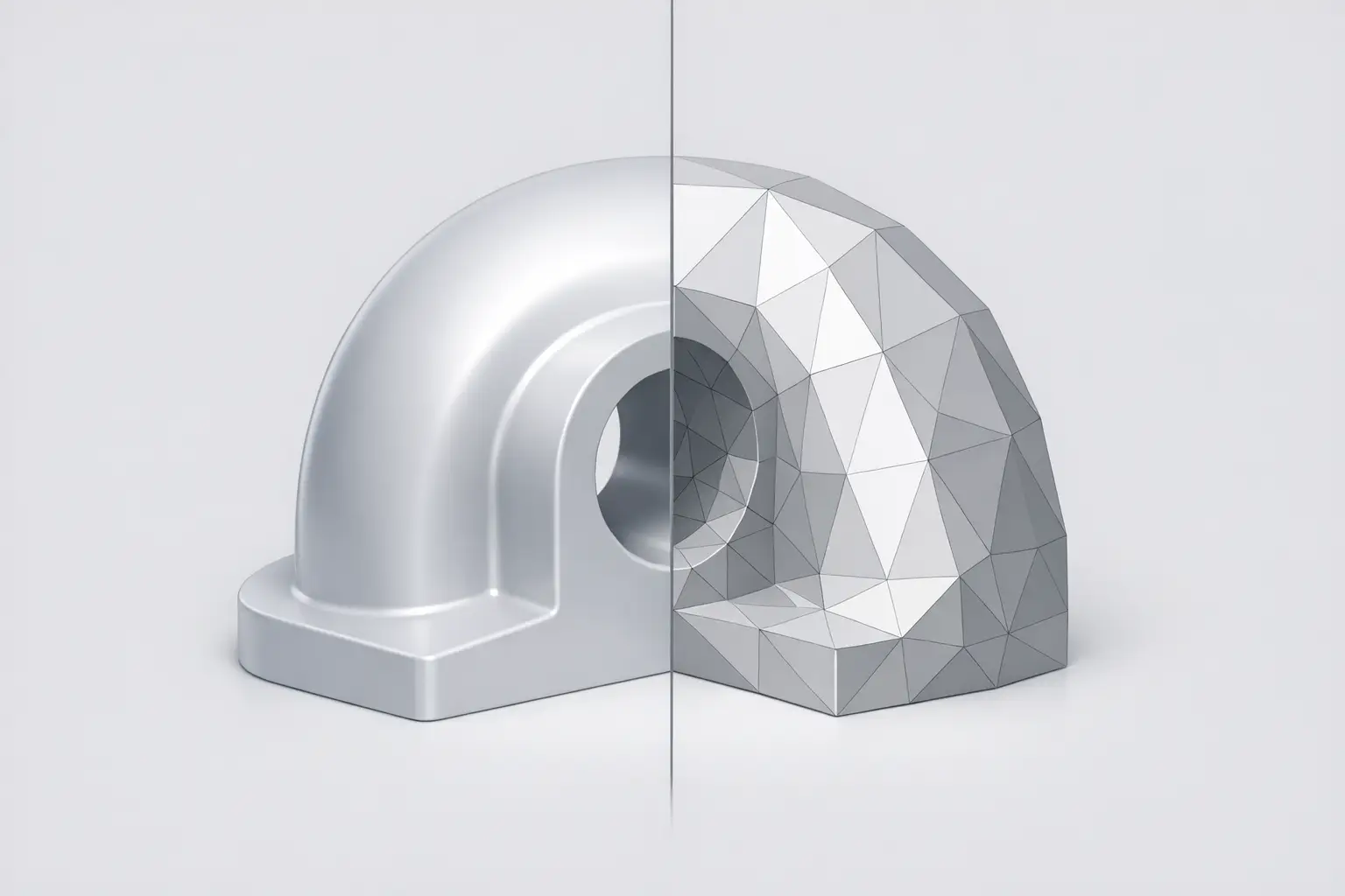
STL (StereoLithography) is a mesh exchange format that represents a 3D model’s surface as a tessellation of triangular facets; increasing surface complexity typically requires more triangles to approximate the shape. [5] STL is commonly encountered in 3D printing pipelines as either ASCII or binary, with binary widely used because it is more compact. [1] Standard STL is unitless and lacks standard color or texture support, which can cause scale and appearance loss during interchange. [4][1]
Overview — What an STL File Is (and Is Not)
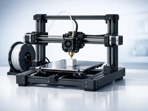
An STL file encodes a triangular mesh intended for geometric interchange into downstream tools such as slicers used in additive manufacturing workflows. Rather than storing parametric or feature-based CAD intent, STL stores only a set of triangles that approximate the exterior surface of a model. [5] The format exists in two variants (ASCII and binary), but both convey essentially the same mesh concept. [1]
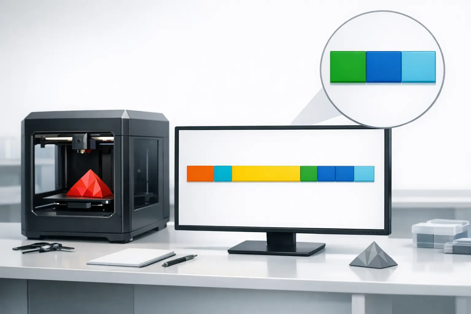
In typical use, a CAD or scan-derived model is tessellated into facets, then consumed by slicing software to generate manufacturing toolpaths. STL’s usefulness comes from being widely implemented and simple to interpret as a triangle list, but it is also a reduction: mesh-only formats (including .stl) do not preserve precise boundary representation (B-Rep) geometry, so face-level operations available in CAD may be unavailable after export. [8] Because curved surfaces are approximated by planar triangles, increasing triangle count improves geometric fidelity while increasing computational and management complexity. [5]
History and Documentation Status
STL was developed by 3D Systems in 1987 and became associated with early stereolithography workflows. [6] The format was first documented by 3D Systems in the StereoLithography Interface Specification in 1988, with a second edition published in 1989. [1] The Library of Congress describes STL as originating with Charles (Chuck) Hull of 3D Systems and characterizes it as proprietary in origin but openly documented in practice, with no formal, modern governance structure to enforce uniform behavior across implementations. [1]
File Identification — Extensions, Media Types, and Variants
The conventional file extension is .stl, and the registered media type includes the stl file extension. [3] In practice, the same extension is used for both ASCII and binary encodings, so identification by extension alone does not determine which variant a file uses. [1]
The Internet media type (often discussed in Multipurpose Internet Mail Extensions (MIME) terms) is model/stl. [3] The IANA registry shows model/stl as registered on 2018-03-06 and last updated on 2022-09-20, and the Library of Congress notes that registration occurred in preparation for encapsulating STL models in Digital Imaging and Communications in Medicine (DICOM) workflows. [3][1]
Data Model and Semantics (Triangles, Normals, Units, Metadata)
At the data-model level, STL represents a surface as a collection of triangular facets (a triangular mesh). Each facet is typically described by three vertices and an associated triangle normal, but the representation remains surface-only: the file does not, by itself, guarantee that the mesh is closed, manifold, or watertight, even if those properties are required by downstream slicing or manufacturing operations. STL’s surface approximation is the central trade-off: higher-curvature or more detailed surfaces generally require finer tessellation (more triangles) to reduce visible faceting. [5]
Facet orientation is a key semantic convention used for “inside” versus “outside.” A common convention is that the facet normal points outward and that the three vertices of a triangle are listed counterclockwise when the facet is viewed from the outside, following the right-hand rule. [4] When exporters or processors violate or ignore these conventions, downstream software may infer incorrect interior/exterior regions, contributing to slicing artifacts or inverted shells.
STL coordinates are unitless: the format does not contain any scale information, and coordinates are in arbitrary units. [4] As a result, importers and slicers often apply assumed units; for example, the Slicer 2 user guide states that STL files do not contain units and that the application defaults to millimeters. [7] STL also provides no standard support for descriptive metadata; in the binary variant, the format begins with an 80-character line sometimes used as a description, but this does not constitute standardized metadata. [2] Standard STL also does not have standard support for colors or textures, limiting its ability to carry appearance information through a pipeline. [1]
What STL cannot represent (standard behavior)
- Color/texture (standard STL has no standard support for colors or textures). [1]
- Units/scale (coordinates are arbitrary; many tools assume defaults such as millimeters). [4][7]
- Scene / multiple objects (STL can define only a single object, not a multi-object scene). [1]
- Rich metadata (no standard descriptive metadata; binary header is sometimes used informally). [2]
Binary STL — Byte-Level Layout
Binary STL is an implementation-oriented encoding with fixed-size records, which makes it straightforward to parse when the endianness and field sizes are honored. A binary STL begins with an 80-character header, followed by a triangle count stored as a 32-bit little-endian integer. [2] Each triangle (facet) record is 50 bytes and is composed of twelve 32-bit little-endian floats: three floats for the facet normal vector and nine floats for the three vertex coordinates. [2] The record ends with a 2-byte unsigned integer commonly called the “attribute byte count.” [2] Historical practice descriptions note that this attribute byte count should be set to zero; when it is not, or when readers interpret it inconsistently, interoperability problems can occur even if the vertex and normal data are otherwise well-formed. [4]
Binary STL Record Layout
| Offset/Field | Type | Size (bytes) | Notes |
|---|---|---|---|
| File header | Character data | 80 | 80-character header; sometimes used as a description but not standardized metadata. [2] |
| Triangle count | Unsigned integer (little-endian) | 4 | 32-bit little-endian triangle count. [2] |
| Facet normal | 32-bit float × 3 (little-endian) | 12 | Part of “twelve 32-bit floats” per facet (normal + vertices). [2] |
| Vertex 1 | 32-bit float × 3 (little-endian) | 12 | First vertex position (x, y, z) as floats. [2] |
| Vertex 2 | 32-bit float × 3 (little-endian) | 12 | Second vertex position (x, y, z) as floats. [2] |
| Vertex 3 | 32-bit float × 3 (little-endian) | 12 | Third vertex position (x, y, z) as floats. [2] |
| Attribute byte count | Unsigned integer | 2 | “Attribute byte count” ends the 50-byte triangle record; often expected to be zero in practice. [2][4] |
ASCII STL — Grammar and Practical Parsing Notes
ASCII STL is a human-readable encoding intended to represent the same triangle-and-normal semantics as binary STL, typically using a solid block containing one or more facet blocks. Both ASCII and binary STL are recognized variants, although binary is more common in practice due to compactness. [1] Conceptually, an ASCII file expresses a list of facets where each facet provides a facet normal and an outer loop of three vertex lines, then closes with endfacet and concludes with endsolid.
A minimal, illustrative fragment (writer-created) is shown below; as with binary STL, consistent interpretation depends on the orientation conventions used for normals and vertex ordering (right-hand rule, counterclockwise when viewed from outside). [4]
solid examplepart
facet normal 0 0 1
outer loop
vertex 0 0 0
vertex 1 0 0
vertex 0 1 0
endloop
endfacet
endsolid examplepart
Interoperability Failures, Validation, and Repair
STL interoperability issues often arise at the boundary between a geometric source model and its tessellated mesh. Academic discussion of STL quality problems includes a 2003 “Analysis of STL files” abstract noting that CAD tessellation used to generate STL can produce defects such as gaps or holes that lead to open loops. [10] Such defects are significant because slicing generally relies on consistent cross-sections through a closed surface; missing triangles, cracks, or self-intersections can prevent robust inside/outside classification during slicing.
Normal and orientation problems are another frequent failure mode. Because many pipelines treat the triangle normal and vertex order as signals for which side of a facet is “outside,” inconsistent application of the outward-normal, counterclockwise convention can yield flipped normals, inverted shells, or ambiguous regions. [4] In practice, some software recalculates normals from vertex order, while other software trusts the stored normal, so a mismatch between the two can propagate differently across tools.
Scale and optional-field ambiguity further complicate interchange. STL carries coordinates in arbitrary units with no embedded scale, and slicers may default to assumed units; Slicer 2, for example, defaults to millimeters and explicitly notes that STL files do not contain units. [4][7] Binary parsing can also be disrupted when the attribute byte count is not treated as expected; historical descriptions state it should be set to zero, but not all producers follow the same convention. [4]
Pre-export / pre-slice STL validation checklist
- Confirm the mesh is manifold and watertight (closed surface without unintended holes), since STL itself does not guarantee these properties and tessellation can introduce gaps. [10]
- Check for consistent facet orientation (outward-facing triangle normals and consistent vertex winding per the right-hand rule) to avoid flipped regions. [4]
- Verify unit agreement across the pipeline (CAD/export assumptions versus slicer import defaults), because STL has arbitrary units and slicers may assume millimeters. [4][7]
- Review triangle density trade-offs (tessellation coarseness versus faceting and processing load), since surfaces are approximated by triangles and complexity typically increases triangle count. [5]
- For binary STL, verify that per-triangle records are well-formed and that the attribute byte count is handled consistently, noting the common expectation that it is zero. [4]
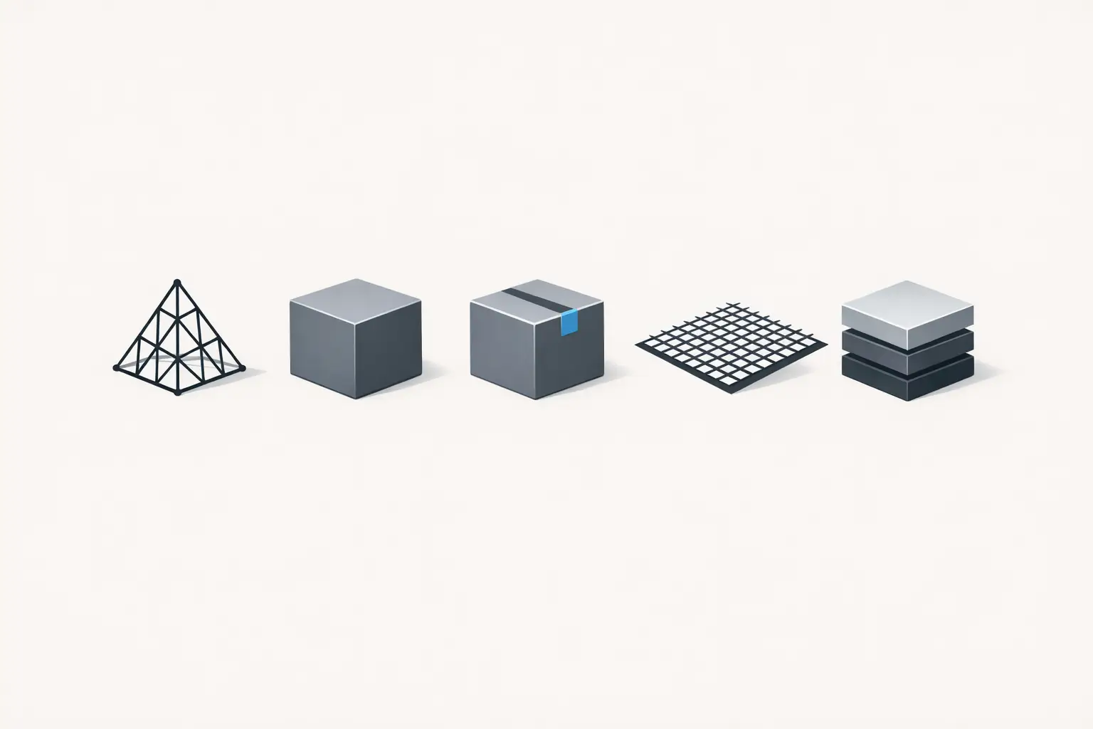
Alternatives and Selection Guidance (STL vs STEP vs 3MF vs AMF/OBJ)
STL remains common as a lowest-common-denominator mesh interchange into slicing workflows, but its limitations motivate alternative formats when richer semantics are required: STL is unitless, cannot represent multi-object scenes, and lacks standard color/texture support. [4][1] For engineering and downstream editability, a B-Rep exchange such as STEP is often preferred because mesh-only formats (including .stl) do not contain precise B-Rep geometry. [8] For 3D printing packaging and extensibility, 3MF contrasts with STL’s flat triangle stream by requiring a ZIP container and constraining compression methods (Deflate (8) or stored (0)) under Open Packaging Conventions (OPC) rules. [9]
STL vs Alternatives
| Format | Geometry & scene | Units & appearance | Container & notes |
|---|---|---|---|
| STL | Mesh (triangular facets); single object only. [1] | Units: no (arbitrary units). [4] Appearance: no standard color/texture. [1] | Flat file (ASCII or binary). Typical use: broad mesh interchange to slicers. Key limitation: unitless, mesh-only, minimal semantics. [4] |
| STEP | B-Rep (precise geometry). [8] Scene/assemblies: No reliable figure found. | Units: No reliable figure found. Appearance: No reliable figure found. | Packaging/container: No reliable figure found. Typical use: engineering exchange preserving B-Rep intent. Key limitation: may not be accepted by mesh-only slicer workflows. [8] |
| OBJ | Mesh; scene support: No reliable figure found. | Units: No reliable figure found. Appearance: No reliable figure found. | Container: No reliable figure found. Typical use: mesh interchange in graphics and some print pipelines. Key limitation: No reliable figure found. |
| 3MF | Mesh-based print description; scene support: No reliable figure found. | Units: No reliable figure found. Appearance: No reliable figure found. | Must use ZIP; compression method may be Deflate (8) or stored (0). [9] Typical use: packaged 3D manufacturing exchange. Key limitation: requires ZIP-based container handling. [9] |
| AMF | Geometry type: No reliable figure found. Scene support: No reliable figure found. | Units: No reliable figure found. Appearance: No reliable figure found. | Container: No reliable figure found. Typical use: No reliable figure found. Key limitation: No reliable figure found. |
Q&A (FAQ)
What is an STL file format in 3D printing workflows?
An STL file is a mesh representation that approximates a model’s surface using triangular facets, with more complex surfaces generally requiring more triangles. [5] In 3D printing workflows, STL commonly appears as either ASCII or binary and is used as an interchange step between CAD/tessellation output and slicing software. [1]
Binary STL vs ASCII STL — what is the difference and why does it matter?
STL has two variants, ASCII and binary, and many tools favor binary because it is more compact. [1] The difference matters operationally because binary STL has a fixed byte-level layout (including an 80-character header, a 32-bit little-endian triangle count, and fixed-size triangle records), enabling deterministic parsing when correctly implemented. [2]
Does an STL file contain units (mm/inches), and why do models import at the wrong scale?
STL does not contain scale information; its coordinates are in arbitrary units. [4] Importers therefore apply assumptions, and Slicer 2 explicitly notes that STL files do not contain units and defaults to millimeters, which can produce scaling mismatches when the exporter and importer assume different units. [7]
What is the model/stl MIME type and when was it registered?
model/stl is the registered Internet media type for STL, associated with the .stl file extension. [3] IANA lists it as registered on 2018-03-06 and last updated on 2022-09-20. [3]
Expert — How is a binary STL triangle encoded at the byte level?
A binary STL starts with an 80-character header and a 32-bit little-endian triangle count. [2] Each triangle record is 50 bytes and includes twelve 32-bit little-endian floats (three for the normal and nine for three vertices), followed by a 2-byte unsigned integer attribute byte count. [2]
Expert — Why do STL exports sometimes contain holes or non-manifold geometry, and what does “repair” address?
STL generation commonly relies on tessellation from a CAD model, and a 2003 “Analysis of STL files” abstract describes defects such as gaps or holes that lead to open loops. [10] “Repair” generally refers to mesh-processing steps that attempt to resolve such issues (e.g., closing holes and restoring consistent topology) so that slicing can derive coherent cross-sections from a watertight, manifold surface.
Sources
- Library of Congress — STL (STereoLithography) File Format Family
- Library of Congress — STL (STereoLithography) Binary File Format
- IANA — model/stl Media Type
- Fabbers — STL File Format (Description and Notes)
- 3D Systems Quickparts — What is an STL File?
- threedy Documentation — STL
- ORNL Slicer 2 — User Guide (PDF)
- Stratasys Support — Adjusting FDM print settings (notes on mesh formats and B-Rep)
- 3MF Consortium — 3MF Core Specification v1.3.0 (PDF)
- BibSonomy — “Analysis of STL files” (2003) entry/abstract