Summary (direct answer)
A pellet 3D printer is a material extrusion (MEX) additive manufacturing system that replaces filament with polymer granules (pellets) and typically meters melt using a rotating screw, a process described in the literature as fused particle fabrication (FPF) or fused granular fabrication (FGF). [2] It is used primarily to increase deposition throughput and to broaden feedstock options (including commodity and recycled pellets), but it commonly trades off surface finish and fine-feature resolution compared with small-nozzle filament printing. [1][2]
Historical Background
Industrial-scale pellet extrusion became prominent in large-format additive manufacturing (LFAM) through projects such as Cincinnati Incorporated and Oak Ridge National Laboratory (ORNL)’s Big Area Additive Manufacturing (BAAM), described in 2014 with a working area of 6.6 ft × 13.1 ft × 2.9 ft and an extrusion rate of about 10 pounds per hour. [5] In later professional coverage, the original BAAM footprint was summarized as roughly 6 ft × 13 ft × 3 ft at up to 10 pounds/hour, while a second-generation system was described with an 8 ft × 20 ft × 6 ft build volume and a print rate up to 100 pounds/hour. [6]
BAAM’s visibility was reinforced by ORNL’s announcement that the BAAM-CI system was among its 2015 R&D 100 Award winners (announcement dated 2015-11-16). [7] In parallel, academic and vendor usage diversified: “BAAM” is often used as a program or system name, while “FPF” and “FGF” are used as process descriptors for screw-driven deposition of particles/granules. [2]
Core Principle (How Pellet Extrusion Works)
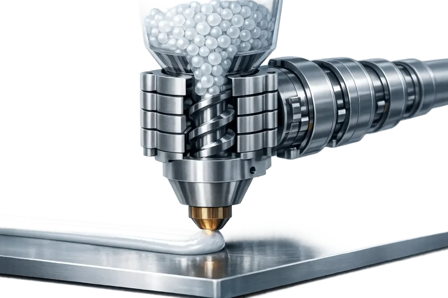
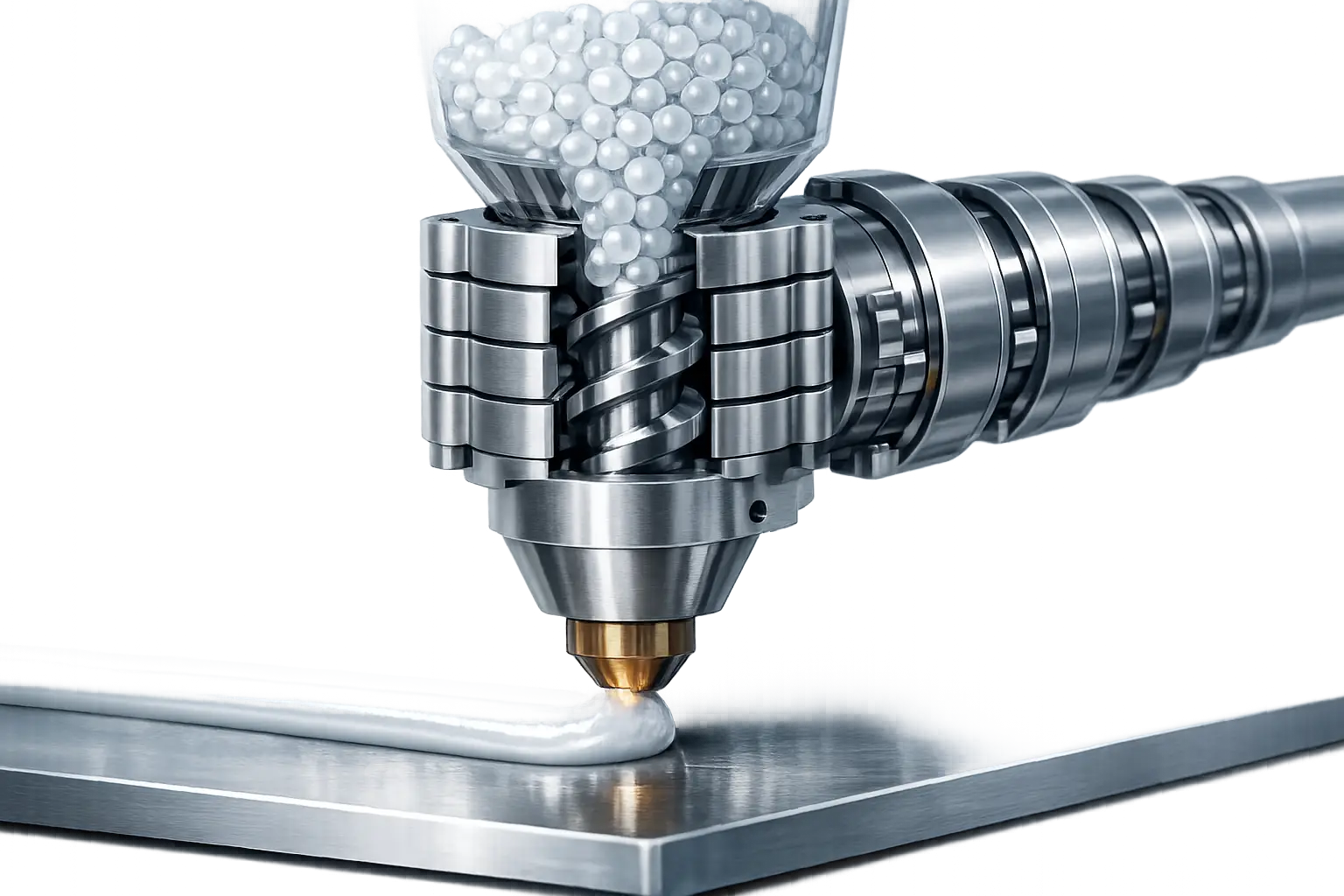
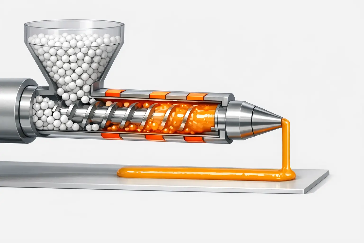
Pellet extrusion printing converts discrete polymer particles into a deposited bead by combining controlled feeding, melting, and metering in a continuous process. Pellets are stored in a hopper and delivered into an extruder barrel, where a rotating screw conveys material forward through heated zones. As the pellets heat, they transition from solid particles to a viscous melt; the screw simultaneously mixes and pressurizes the melt before forcing it through a nozzle to form a bead that is placed along a toolpath. In contrast to filament-based systems (where a drive gear pushes a constant-diameter filament into a hotend), screw extrusion meters material by screw speed, torque, and back-pressure, and it can be fed by gravity or assisted feeding depending on system scale and pellet flow characteristics. Practical pellet size ranges are commonly specified rather than assumed: one commercial system specifies pellet feedstock of Ø 2–6 mm, and documentation for a widely used pellet printhead describes “ideal pellets” as 3–5 mm diameter spherical particles. [9][14] The same fundamental melt-and-meter principle spans both large-nozzle industrial heads (for example, a robotic extruder line listing nozzle diameters of 8–20 mm) and smaller pellet heads that accept millimeter-class nozzles. [8]
Hardware Architecture (Subsystems)
Pellet printers are typically organized around the extruder (screw, barrel, heaters, nozzle) and the feed and thermal subsystems that keep melt delivery stable. At large scale, manufacturers may publish bead geometry and deposition framing explicitly; for example, Thermwood’s LSAM specifications include a representative bead of 0.200 inch thickness and 0.830 inch width, and also describe print-layer lap lengths up to 200 feet. [3] Some pellet heads are specified with high melt temperatures (for example, 400°C-class heaters), and smaller printheads may publish higher maximum hotend ratings (for example, up to 500°C for a pellet extruder product line), making thermal management and guarding central design concerns. [8][12] Enclosures and heated build chambers are also used in some systems; one pellet printer specification lists a chamber temperature maximum of 150°C. [9]
Feeding and material conditioning hardware is a differentiator because pellet quality and moisture content directly affect flow and extrusion stability. Documentation for a pellet extruder emphasizes pellet geometry and handling constraints (including ideal pellet shape/diameter), and industrial vendors may offer dedicated drying equipment; one robotic extruder announcement describes an optional pellet dryer of 400 Liter capacity. [14][8] Motion platforms span gantry machines, CNC-style hybrids, and robot-mounted extruders: Thermwood LSAM, for example, publishes separate printing and trimming envelopes, reflecting a combined additive and subtractive architecture where a part can be deposited and then machined within the same overall system. [3]
Technical Performance (What Vendors Actually Publish)
Vendor-published performance data for pellet extrusion tends to emphasize throughput and operating envelopes, while precision metrics are often absent. Throughput is reported as mass flow (kg/h or lb/h) or, less often, as bead-length rate under a stated bead geometry. Thermwood specifies that a 40 mm melt core “processes over 200 pounds/hour” (material-dependent) and also states a 70 mm melt core has been “operated at rates of over 500 pounds per hour”; a separate Thermwood announcement reports 60 mm melt core testing at 480 to 570 pounds/hour and lists the standard 40 mm melt core as 190 to 210 pounds/hour, with bead-rate examples of 40–50 feet/min (standard bead) and “well over 100 feet” of bead per minute. [3][4] Other published examples span smaller to mid-scale systems: CEAD lists a maximum output of 12 kg/hr for an E25 extruder, while the E50 is described with a measured 84 kilograms/hour using PP30%GF at 60% of max speed, along with nozzle sizes of 8–20 mm and a temperature reach of 400°C. [8] A large-volume pellet printer lists a maximum output of 3.8 kg/h (stated with ABS and a 5 mm nozzle), a hotend maximum of 350°C, and a maximum print speed of 100 mm/s, while a pellet extrusion system listing states a maximum extrusion rate of 18 lbs/hour. [9][10] An enclosed industrial pellet printer model page lists throughput up to 15 lbs/hr (6.8 kg/hr), a maximum extruder temperature of 752°F (400°C), and a maximum chamber temperature of 203°F (95°C). [11] At printhead scale, Dyze Design lists a Pulsar pellet extruder max flow up to 500 mm³/s (2.5 kg/h) with “3D700 PLA at 200°C,” and also lists a maximum temperature of 500°C. [12] Across these sources, dimensional accuracy, repeatability, and standardized mechanical-property baselines are frequently not published as simple, comparable figures; for many systems, “No reliable figure found” is the appropriate entry for accuracy unless a primary datasheet explicitly states it.
Mandatory Comparison Table
| System (type) | Build volume / envelope | Throughput (published) | Selected published specs / notes |
|---|---|---|---|
| Thermwood LSAM (LFAM hybrid system) | Printing: 10 ft wide, 5 ft high, up to 100 ft long; trimming: 10 ft wide, 6 ft high (same length as printing envelope). [3] | 40 mm melt core: processes over 200 pounds/hour (material-dependent); 70 mm melt core: over 500 pounds per hour (manufacturer statement). [3] | Example bead: 0.200 inch thick and 0.830 inch wide; print-layer lap length up to 200 feet. [3] |
| CEAD E25 / E50 (robot/CNC-mounted extruders) | No reliable figure found. | E25 maximum output: 12 kg/hr; E50 measured 84 kilograms/hour with PP30%GF at 60% of max speed. [8] | Nozzle sizes 8–20 mm; temperature reach 400°C; motor 15 kW; optional pellet dryer 400 Liter. [8] |
| WASP 3MT HDP (pellet printer) | Ø 1000 × h 1000 mm. [9] | Max output 3.8 kg/h (ABS WASP, 5 mm nozzle). [9] | Nozzles 2/3/5 mm; pellet Ø 2–6 mm; layer resolution 0.5–2.5 mm; hotend max 350°C; chamber temp max 150°C; print speed 100 mm/s; travel 200 mm/s. [9] |
| Titan Robotics pellet extrusion system (system listing) | No reliable figure found. | Maximum extrusion rate 18 lbs/hour. [10] | “Reduces material costs ten-fold” (attributed marketing claim). [10] |
| JuggerBot Tradesman Series P3-44 (enclosed pellet printer) | 36 × 48 × 48 in (914 × 1219 × 1219 mm). [11] | Up to 15 lbs/hr (6.8 kg/hr). [11] | Max extruder temp 752°F (400°C); max chamber temp 203°F (95°C); suggested layer height 0.030–0.089 in (0.75–2.25 mm). [11] |
| Dyze Design Pulsar (pellet printhead) | No reliable figure found. | Up to 500 mm³/s (2.5 kg/h) with 3D700 PLA at 200°C. [12] | Max temperature 500°C; heating power 1100 W; nozzle sizes include 1/1.5/2/3/4/5 mm. [12] |
The table reflects what primary pages and peer-reviewed sources explicitly publish: throughput, envelope, nozzle class, and temperatures are relatively common, while accuracy and repeatability are often not stated in a directly comparable form and should be requested as vendor-provided test results rather than inferred.
Materials and Feedstock Considerations
Pellet printing is often described as “granule 3D printing” because feedstock geometry, bulk density, and moisture condition influence extrusion stability. A manufacturer example lists acceptable pellet size as Ø 2–6 mm, while pellet extruder documentation specifies “ideal pellets” as 3–5 mm diameter spherical particles, implying that consistent shape and size distribution are treated as process inputs rather than incidental details. [9][14] Peer-reviewed work also reports pellet dimensions as part of experimental context, including recycled ABS pellets “approximately 3 mm” and recycled PET pellets “~4 mm,” illustrating that recycled feedstocks can be processed when particle geometry is controlled to a usable range. [2]
Moisture control is commonly treated as necessary for stable extrusion and part quality even when detailed drying curves are not published in short product pages. Industrial pellet extrusion offerings may therefore be paired with material handling and conditioning subsystems, including optional dedicated dryers (for example, a 400 Liter pellet dryer offered alongside a robotic extruder platform). [8] Composite pellets (such as glass-fiber-filled polypropylene) are also explicitly used in performance claims; CEAD’s published E50 test figure is given for PP30%GF at a stated fraction of maximum speed, underscoring that output values are conditional on both polymer family and filler content. [8]
Process Planning (Slicing, Toolpaths, Calibration)
Toolpath planning for pellet deposition is dominated by bead geometry and thermal history rather than by the fine-feature assumptions common in desktop fused filament fabrication (FFF). With larger nozzles, bead width and layer height increase, which can reduce build time by increasing volumetric deposition per unit path length, but also limits minimum feature size and increases the visibility of stair-stepping on sloped surfaces. Vendor specifications frequently communicate “resolution” through permissible layer-height bands: one pellet printer lists layer resolution of 0.5–2.5 mm (nozzle-dependent), and an enclosed industrial model lists suggested layer height of 0.030–0.089 in (0.75–2.25 mm). [9][11] In very high-throughput systems, bead geometry may be published directly as a thick, wide road (for example, 0.200 inch thickness and 0.830 inch width), aligning slicer strategy with near-net-shape deposition rather than fine contour replication. [3]
Peer-reviewed comparisons support the general claim that pellets can increase deposition rate when the extrusion system and nozzle are sized for it. In one study framed around fused particle fabrication/fused granular fabrication, volumetric deposition is reported at 35 mm³/s at a print speed of approximately 20 mm/s, while a stated “traditional FFF” baseline (50 mm/s, 0.2 mm layer height, 0.4 mm nozzle) averages 4 mm³/s, described as an 8.75× factor. [2] Such comparisons are sensitive to nozzle diameter, melt temperature, and bead cooling: higher deposition rates can increase residual heat in the part, potentially requiring adjusted dwell time, reduced stacking rate, or environmental temperature control (for example, heated chambers) to manage warping and interlayer bonding consistency. A published chamber temperature maximum of 150°C on a large pellet printer illustrates that some systems provide thermal enclosure capability as a specified feature rather than a user modification. [9]
Calibration and retraction behavior differ materially from filament systems because screw-driven melt delivery does not necessarily respond to short reverse commands in the same way a filament drive does. Dyze documentation for a pellet extruder states that retraction must not be used, a constraint that affects how slicers manage pressure, start/stop points, and stringing risk in travel moves. [14] The same documentation also provides specific examples of thermal expansion compensation values (0.32 mm at 200°C, 0.49 mm at 300°C, and 0.66 mm at 400°C), reflecting that mechanical offsets may be temperature-dependent and may need to be managed as part of commissioning rather than treated as constant machine geometry. [14] Some documentation also includes firmware-level constraints (for example, a feed rate capped at 150 mm/s), indicating that achievable deposition behavior can be bounded by control-stack settings in addition to heater power and screw capability. [14]
Applications (Where Pellet Printers Are Used)
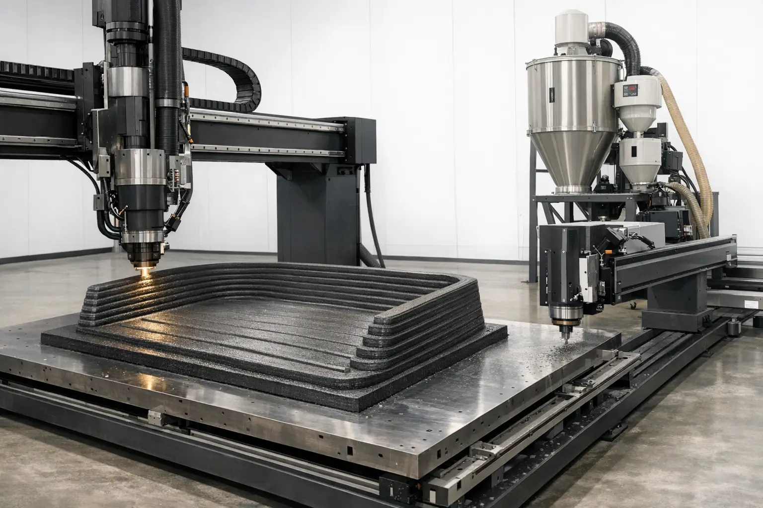
Pellet extrusion is often selected for applications where high deposition rate and low feedstock cost are prioritized over fine surface quality, and where parts are large enough that conventional filament logistics (spool handling, frequent changeover) become limiting. Hybrid workflows are a common industrial pattern: Thermwood LSAM publishes both printing and trimming envelopes on the same platform, supporting a process in which a near-net-shape is printed and then machined to final tolerances within a shared coordinate system. [3] In this context, pellet deposition provides bulk material quickly, while subtractive finishing provides surface quality, datum accuracy, and tighter fits than bead deposition alone typically yields.
Pellet systems are also used for large molds and tooling patterns, jigs and fixtures, and large prototypes where “large format prints” are required and where feedstock flexibility is valuable. Manufacturer marketing sometimes highlights potential material-cost reductions (for example, claims of granules being “up to 10 times” cheaper than filaments, or “ten-fold” cost reduction), but such statements are vendor-specific and should not be treated as general industry averages without independent datasets. [9][10] Research and review literature describes the broader technical landscape, including screw-extrusion FGF trends and materials considerations, providing a taxonomy backdrop for why these systems are frequently discussed under LFAM rather than small-part prototyping. [15]
Limitations, Safety, and Standards
Limitations of pellet extrusion are primarily linked to bead scale, melt control, and process dynamics. Large nozzle diameters (including the 8–20 mm class published for one industrial extruder line) constrain minimum wall thickness, corner fidelity, and text/feature reproduction, and they typically require subsequent machining or design concessions for assemblies. [8] Even in smaller pellet systems, stated layer-height bands in the ~0.5–2.5 mm or ~0.75–2.25 mm range indicate that surface finish will generally be coarser than typical 0.2 mm filament printing unless secondary finishing is applied. [9][11] For many commercial systems, dimensional accuracy, repeatability, and standardized mechanical properties are not published as single headline figures; when absent, “No reliable figure found” is preferable to extrapolation.
Safety concerns include high-temperature components and mechanical hazards associated with rotating screws, feed mechanisms, and high-force motion systems. Published temperature capabilities can be used to bound hazard potential: examples include 400°C-class extruder temperature ratings on industrial pellet printers and a 500°C maximum temperature published for a pellet printhead product. [11][12] Operational constraints published in pellet extruder documentation (such as prohibition of retraction and firmware feed-rate caps) are also relevant to safe commissioning because they affect how the system behaves during starts/stops and how users should configure toolpaths to avoid unintended extrusion behavior. [14]
Standard terminology is commonly anchored using ISO/ASTM 52900:2021 (edition 2), published 2021-11 and listed as confirmed in 2025, which is used in practice to normalize additive manufacturing vocabulary such as “material extrusion (MEX)” when describing pellet extrusion as part of the broader MEX family. [1]
Buying/Selection Criteria (Spec-Driven Checklist)
Selection of a pellet 3D printer or pellet extruder is typically driven by the intersection of throughput targets, nozzle class, thermal capability, and envelope, with material conditioning and software constraints treated as first-order requirements. Published figures show a wide spread: from a pellet printer example listing 3.8 kg/h under stated conditions, to industrial vendor statements exceeding 200 pounds/hour and 500 pounds/hour, to robot-mounted extruder reporting in kg/hr with explicit material context (PP30%GF) and nozzle diameter class (8–20 mm). [9][3][8] Because accuracy and repeatability are frequently not published, procurement commonly requires requesting test artifacts, tolerance reports, and process windows rather than relying on nominal claims.
-
Minimum specs to request from a pellet-printer vendor
-
Throughput with stated material, nozzle diameter, temperature, and duty cycle (e.g., vendor statements in lb/h or kg/hr, or conditioned claims such as “with PLA at 200°C”). [3][8][12]
-
Nozzle diameter options and any published bead geometry (width/height) ranges. [8][3]
-
Supported pellet size/shape constraints and feeding method assumptions (gravity vs assisted conveying). [9][14]
-
Dryer requirements and any offered dryer capacity (where applicable). [8]
-
Maximum extruder temperature and maximum chamber temperature (if enclosed/heated). [11][9][12]
-
Control limitations relevant to toolpaths (e.g., whether retraction is permitted, and any feed-rate caps). [14]
-
Dimensional accuracy and repeatability reports (if not published, request measured data; otherwise treat as “No reliable figure found.”)
-
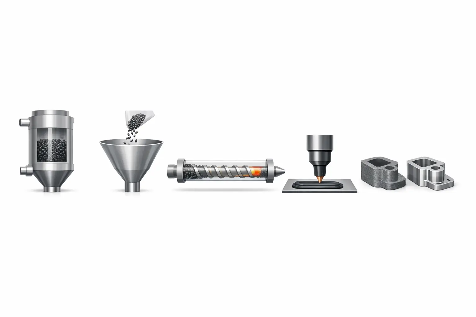
Pellet printing process flow
- Dry and condition pellets to the required moisture level (equipment may be offered as an option). [8]
- Convey pellets to the hopper (gravity feeding and pellet geometry constraints are commonly specified). [14]
- Melt and meter material via screw extrusion through heated zones to the nozzle. [12]
- Deposit a bead along toolpaths; layer height and bead size are selected to balance build time and surface finish. [9]
- Cool and stabilize the part thermally (sometimes supported by heated chambers). [9]
- Finish to final tolerances as required, including machining in hybrid workflows. [3]
FAQ
What is a pellet 3D printer (FGF) and how is it different from FFF?
In the literature, fused particle fabrication (FPF) and fused granular fabrication (FGF) describe extrusion-based printing using particles/granules rather than filament, generally implemented with screw extrusion rather than filament drive gears. [2] It is typically discussed as part of material extrusion (MEX) terminology anchored by ISO/ASTM 52900. [1] A peer-reviewed comparison reports volumetric deposition of 35 mm³/s for an FPF/FGF setup versus an average of 4 mm³/s for a stated “traditional FFF” baseline, illustrating why pellets are often chosen for higher throughput. [2]
What is a pellet extruder’s typical throughput in kg/h or lb/h?
Published examples span a wide range and are condition-dependent. Thermwood states a 40 mm melt core “processes over 200 pounds/hour” and a 70 mm melt core has been operated at over 500 pounds per hour, while CEAD lists 12 kg/hr maximum output for an E25 and a measured 84 kilograms/hour for an E50 test with PP30%GF at 60% of max speed. [3][8] Smaller systems include a published 3.8 kg/h maximum output under stated conditions, a listing of 18 lbs/hour for a pellet extrusion system, “up to 15 lbs/hr (6.8 kg/hr)” for an enclosed pellet printer, and “up to 500 mm³/s (2.5 kg/h)” for a pellet printhead with PLA at 200°C. [9][10][11][12]
What pellet sizes do pellet 3D printers accept?
Published acceptance ranges vary by extruder and feeding method. One pellet printer page specifies pellet feedstock of Ø 2–6 mm, while pellet extruder documentation describes “ideal pellets” as 3–5 mm diameter spherical particles. [9][14] Peer-reviewed experimental reporting includes recycled ABS pellets “approximately 3 mm” and recycled PET pellets “~4 mm.” [2]
Do screw-based pellet extruders support retraction like filament printers? (expert)
Not always. Documentation for a pellet extruder explicitly states that retraction must not be used, indicating that slicer configurations and travel behavior must be adapted to an extrusion system that is not designed to reverse pressure in the same manner as filament-based drives. [14]
How do nozzle diameter and layer height affect surface finish and build time in pellet printing? (expert)
Larger nozzle diameters generally enable higher bead cross-sections and faster bulk deposition, but they increase minimum feature size and typically reduce surface smoothness. Published layer-height guidance reflects this tradeoff: one pellet printer lists layer resolution of 0.5–2.5 mm (nozzle-dependent), and an enclosed industrial pellet printer lists suggested layer height of 0.030–0.089 in (0.75–2.25 mm). [9][11] Industrial extruder offerings may also publish very large nozzle diameter classes (e.g., 8–20 mm), indicating a design intent toward large beads and high throughput rather than fine detail. [8]
Can pellet printing be combined with machining for final tolerances?
Yes, hybrid workflows are explicitly supported in some published system envelopes. Thermwood LSAM provides both printing and trimming envelopes, enabling additive deposition followed by subtractive trimming on the same platform. [3] This approach is commonly used to achieve final dimensions and surface finishes that are difficult to obtain directly from large-bead deposition alone. [3]
Sources
- ISO/ASTM 52900:2021 — Additive manufacturing — General principles — Fundamentals and vocabulary (ISO page)
- Materials (MDPI) — Fused particle fabrication (FPF) / fused granular fabrication (FGF) study and comparisons (2018-08-12)
- Thermwood — LSAM Specifications
- Thermwood Blog — New higher capacity melt core for LSAM print head (2018-12-18)
- Plastics Machinery & Manufacturing — Cincinnati’s new 3-D BAAM tackles extra-big parts (2014-11-30)
- ASME — 3D Footprint Grows with BAAM (2015)
- Oak Ridge National Laboratory — ORNL wins six R&D 100 Awards (2015-11-16)
- CEAD — CEAD launches a new model of the robot extruder: the E50 (2021-06-08)
- WASP — WASP 3MT HDP big 3D printer (specifications)
- DirectIndustry — Titan Robotics pellet extrusion system (product listing)
- JuggerBot 3D — Pellet models (Tradesman Series P3-44 specifications)
- Dyze Design — Pulsar pellet extruder
- Dyze Design — Pulsar Atom pellet extruder
- Dyze Design Docs — Pulsar (documentation)
- ScienceDirect — Screw extrusion fused granulate fabrication: Trends, materials, extruder classification and future development (2025)