Summary (direct answer)
A Cartesian 3D printer is a rectilinear XYZ motion system in which each axis is driven independently, aligning the machine’s kinematics with the Cartesian coordinate system used to describe positions in straight-line coordinates. In Marlin firmware documentation, “Cartesian is the simplest, applying each stepper directly to an axis,” and manufacturer documentation commonly describes Cartesian layouts as designs where “each axis moves independently,” including “bed slinger” variants. [1][2]
Terminology and classification (what “Cartesian” means in 3D printing)
“Cartesian” in 3D printing is a naming convention that links rectilinear machine motion to the Cartesian coordinate system, a method of specifying locations using orthogonal axes associated with René Descartes’ 1637 publication. [4][5] In printer documentation, the term is typically used at the motion-system level (kinematics) to describe serial, decoupled axis control rather than the extrusion process. Marlin, for example, organizes common desktop motion architectures into categories that include Cartesian, Core (H‑Bot), Delta, and SCARA, framing Cartesian as one supported kinematic option among several. [1]
In practical usage, “Cartesian 3D printer” therefore describes how the machine moves (its gantry and/or bed motion), not whether it is Fused Filament Fabrication (FFF) or Fused Deposition Modeling (FDM) hardware. [1]
Historical background (dated milestones that shaped Cartesian printers)
The word “Cartesian” originates from coordinate geometry attributed to Descartes and published in 1637, providing a durable conceptual model for expressing motion along orthogonal axes. [4][5] In desktop 3D printing history, later milestones helped normalize rectilinear, serial-axis mechanisms in open designs: the RepRap project began in 2005 and documented early self-replicating, user-buildable printers that frequently used straightforward axis-by-axis motion control. [6] RepRap Mendel is recorded as printing its first part on 2 October 2009, a frequently cited point in the maturation of hobbyist-style machines. [6] A further landmark for Cartesian-style layouts in consumer FFF printers is the Prusa i3 redesign, released in May 2012, which helped popularize a compact, serviceable frame and an i3-style motion arrangement in which the axes are treated as separable subsystems for mechanics and firmware configuration. [7]
Mechanical principles (how Cartesian motion is implemented)
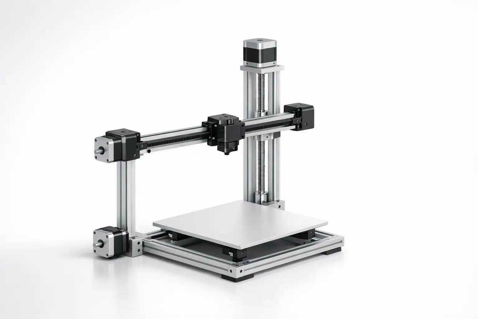
In a Cartesian motion system, each stepper motor is mapped directly to one axis so that commanded movements can be decomposed into independent X, Y, and Z components. [1] This axis decoupling is reflected in common firmware configuration language and in user-level descriptions that emphasize independent axis motion as the defining characteristic. [1][2] Mechanically, that mapping is realized through linear guides and a mix of belt drive stages (often for X and Y) and lead screw or other screw-driven stages (often for Z), though the specific actuator type is a product choice rather than an architectural requirement.
A major design variable within Cartesian kinematics is which major mass moves on which axis. Polymaker’s overview uses “bed slinger” to describe a common Cartesian layout where the bed moves along the Y-axis while the toolhead rides an X-axis gantry, keeping the X toolhead carriage relatively simple while assigning Y motion to the build platform. [2] Other Cartesian layouts instead move a gantry in Y (with the bed typically moving in Z), or keep the gantry fixed while moving only a lightweight toolhead in XY and lifting/lowering the bed in Z; these configurations still qualify as Cartesian when the axes remain independently actuated and controlled. [1][2] Across these variants, homing is commonly implemented with endstops to establish known axis reference positions at startup, and the same kinematic concept can be paired with different frame geometries, guide systems, and maintenance philosophies without changing the underlying “one motor per axis” control model. [1]
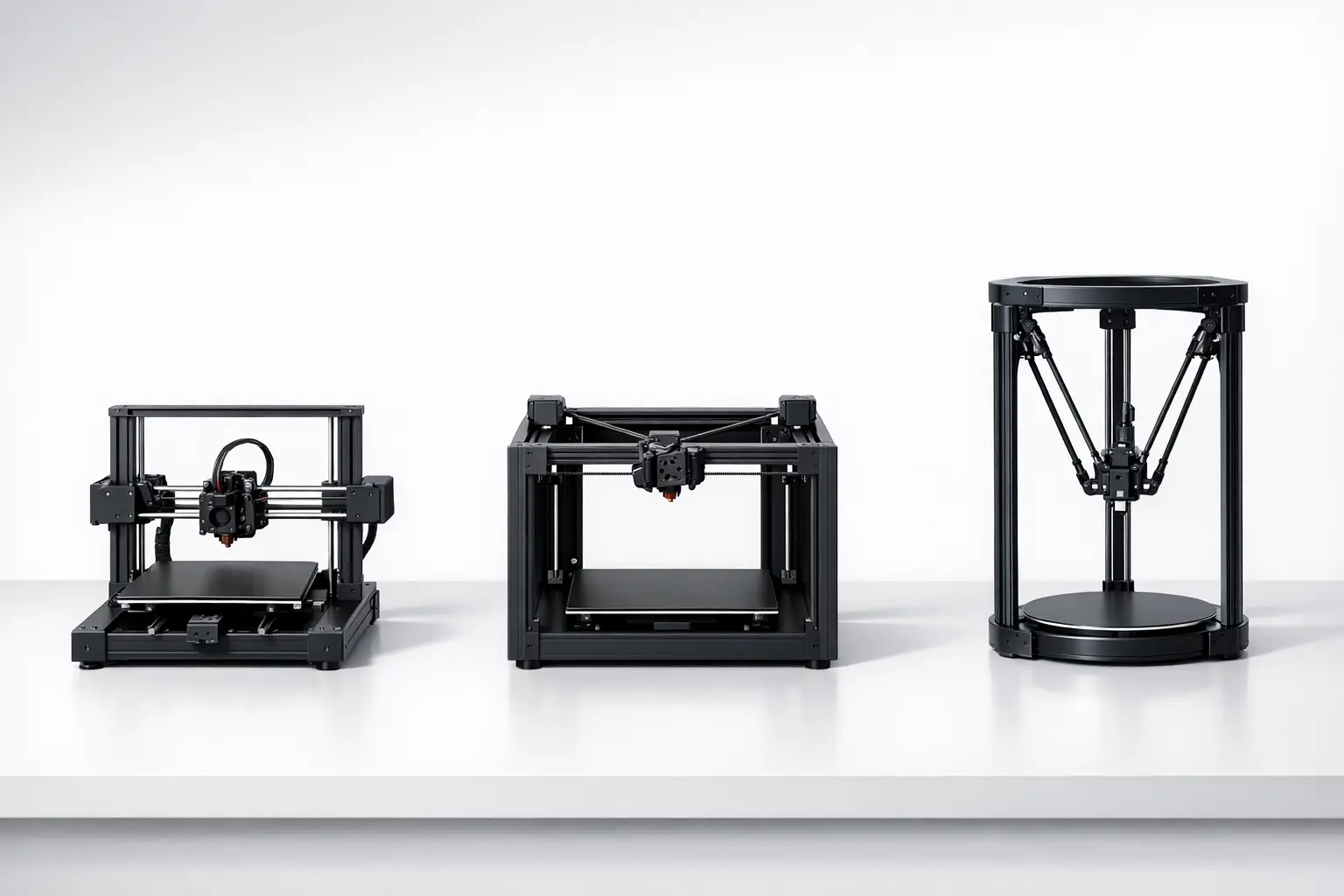
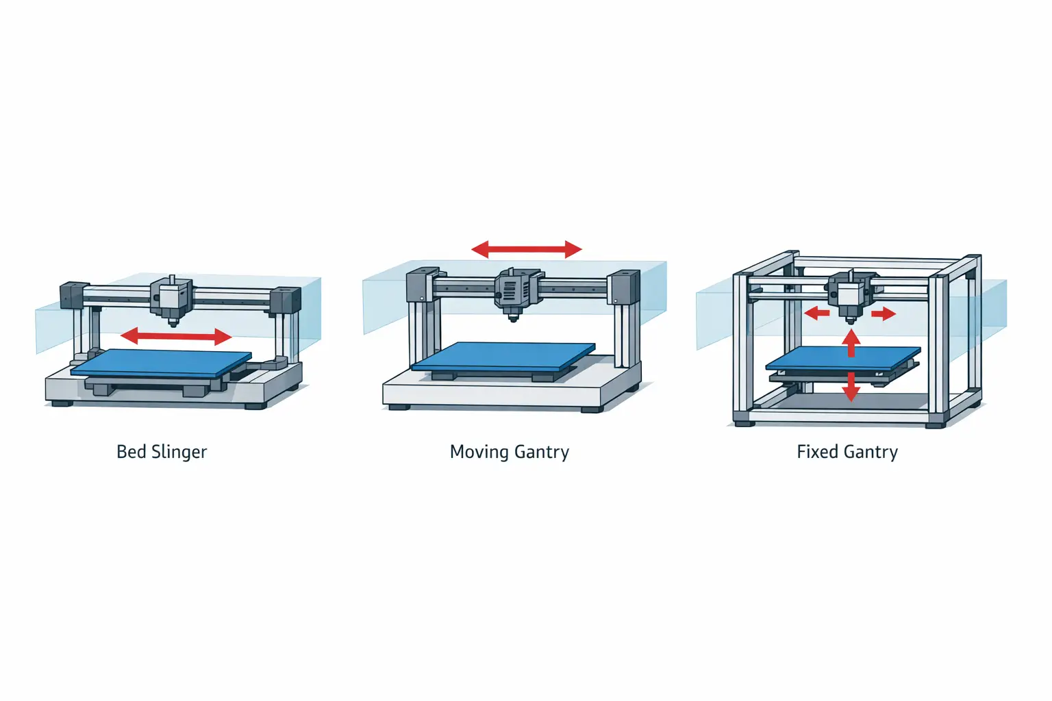
Common Cartesian sub-architectures (non-exhaustive):
- i3-style / bed-slinger (bed moves in Y). [2]
- moving-gantry with bed moving in Z (Cartesian, often confused with CoreXY because both can use a rectangular XY gantry). [1]
- fixed-gantry variants where toolhead moves XY and bed moves Z. [1]
Technical performance patterns (what can be compared, and what cannot)
Many performance specifications associated with a “Cartesian FDM printer” are not inherent to Cartesian kinematics but are product-level consequences of mechanical stiffness, moving mass, drive selection, and control tuning. A common contrast is with CoreXY, which is described by its project documentation as using stationary motors and a belt arrangement intended to reduce moving mass and inertia in the XY system, whereas Cartesian machines typically dedicate a motor directly to each axis. [3][1] Delta mechanisms are also frequently compared against “traditional serial-axis designs” in dynamics and control research; one scientific discussion reports delta robots reaching higher speeds than traditional serial-axis designs in that context, along with reported computation time reduction “up to 23x” and vibration reductions “more than 20%,” which should be interpreted as findings within the paper’s modeled/experimental setup rather than universal guarantees for all printers. [8]
Specification exemplars (anchored examples — clearly attributed)
The numerical specifications commonly discussed for Cartesian printers (build volume, layer height, temperatures, and speeds) are best treated as examples from specific products rather than as “typical Cartesian” values. The examples below illustrate how the same kinematic category spans multiple market segments. [9][10][11]
Example product specifications include an entry-level bed-slinger (Creality Ender‑3 V2), a prosumer i3-style machine (Original Prusa MK4S), and a professional gantry-based system (UltiMaker S5). The Ender‑3 V2 is listed with a print volume of 220 × 220 × 250 mm, a 0.4 mm nozzle diameter, 1.75 mm filament diameter, a maximum traveling speed of 180 mm/s, a maximum nozzle temperature of 255°C, layer thickness of 0.1 to 0.4 mm, and precision of ±0.1 mm. [9] The Original Prusa MK4S is specified with a build volume of 250 × 210 × 220 mm, 1.75 mm filament diameter, layer height of 0.05–0.30 mm, 0.9° X,Y stepper motors, a 0.4 mm nozzle, a maximum nozzle temperature of 290 °C, and a maximum heatbed temperature of 120 °C. [10] The UltiMaker S5 is specified with a build volume of 330 × 240 × 300 mm, 2.85 mm compatible filament diameter, weight of 29.1 kg, maximum power output of 500 W, layer resolution of 60–400 microns, XYZ resolution of 6.9, 6.9, 2.5 micron, nozzle diameters of 0.25/0.4/0.6/0.8 mm, nozzle temperature of 180–280 °C, nozzle heat-up time < 2 minutes, operating sound < 51 dBA, build plate heat-up time < 5 minutes (from 20 to 60 °C), and operating ambient temperature of 15–32 °C. [11]
Cartesian vs CoreXY vs Delta — kinematics coupling, moved mass, calibration characteristics, common implementations
| Motion system | Kinematics coupling | Moved mass (qualitative) | Calibration characteristics and common implementations |
|---|---|---|---|
| Cartesian | Each stepper motor is applied directly to an axis (serial-axis decoupling). [1] | Often includes axis stages where a motor rides on the moving axis, depending on layout. [1] | Setup is commonly framed around independent X/Y/Z motion, homing, and endstops in firmware configuration. [1] Common implementations include i3-style bed-slingers (moving-bed Y-axis) and moving-gantry or fixed-gantry variants. [2] |
| CoreXY | XY motion is belt-coupled so that two motors cooperate to produce X and Y movement. [3] | Project documentation emphasizes stationary motors and reduced moving mass/inertia in the XY system. [3] | Often treated as a distinct kinematics option in firmware alongside Cartesian. [1] Common implementations are belt-driven XY gantries where motor placement is fixed to the frame. [3] |
| Delta | Motion is produced by coordinated movement of multiple arms rather than independent orthogonal axes at the toolhead. [1] | Moving mass is distributed across the arms/carriages, with different inertia tradeoffs than serial-axis designs. [8] | Research comparisons discuss deltas versus “traditional serial-axis designs” in dynamics/control terms, including claims about higher achievable speeds in that context. [8] Common implementations use three vertical towers with linked arms supporting a central effector. [1] |
Applications and selection guidance (use cases tied to architecture)
Cartesian kinematics are commonly presented in firmware and manufacturer descriptions as a baseline motion model for many FFF/FDM-style machines, largely because the independent-axis mapping is straightforward to configure and reason about during setup, homing, and troubleshooting. [1][2] Within that umbrella, bed-slinger designs are often discussed as a common consumer layout, while other Cartesian implementations move the gantry or lift the bed in Z to manage moving mass and packaging constraints differently. [2] Because “Cartesian” is a kinematics label rather than a material or process label, selection discussions are usually better anchored to the specific implementation details (frame stiffness, accessibility, enclosure compatibility, and motion stage arrangement) than to the Cartesian term alone, and comparisons to CoreXY or delta systems typically center on how belt coupling or parallel mechanisms change moved mass and control behavior. [3][8]
Selection/fit checklist (architecture-focused, non-numeric):
- Enclosure friendliness (whether the moving-bed Y-axis requires extra clearance). [2]
- Moving-bed inertia implications (how much mass is accelerated on Y in a bed-slinger layout). [2]
- Maintenance accessibility (belt drive routing, lead screw access, and gantry serviceability). [1]
- Firmware support and kinematics selection (Cartesian vs Core vs Delta vs SCARA in common firmware). [1]
- Upgrade ecosystem compatibility (how readily toolheads, sensors, and motion parts can be changed within the frame concept). [1]
- Multi-material complexity (how added toolheads or feeders interact with moving-gantry versus moving-bed layouts). [1]
Q&A (FAQ)
This FAQ addresses Cartesian 3D printer kinematics: how motion is generated and classified in firmware and documentation, rather than recommending brands or prescribing “best” specifications. Where numerical values are mentioned, they are treated as example product specifications drawn from cited pages, not as universal Cartesian characteristics. [1][2]
1) What is a Cartesian 3D printer (Cartesian motion system) in FDM/FFF?
In Marlin documentation, Cartesian is described as “the simplest, applying each stepper directly to an axis,” which reflects independent, serial-axis control in X, Y, and Z. [1] Manufacturer documentation also describes Cartesian systems in plain language as designs where each axis moves independently, aligning with a rectilinear coordinate model used by many FFF/FDM machines. [2]
2) Is a “bed-slinger” always a Cartesian 3D printer?
“Bed slinger” is commonly described as a Cartesian layout in which the bed moves in the Y-axis while the toolhead moves on the X-axis. [2] In that usage, bed-slinger implies independent axis motion rather than belt-coupled XY behavior, so it is treated as a Cartesian sub-architecture rather than a separate kinematics category. [2]
3) How is CoreXY different from Cartesian motion in 3D printers? (CoreXY vs Cartesian)
Cartesian motion assigns a motor directly to each axis, whereas CoreXY uses a belt-coupled arrangement in which two motors cooperate to produce X and Y motion. [1][3] The CoreXY project description emphasizes stationary motors and reduced moving mass/inertia, which is a different design goal from the axis-dedicated motor mapping typical of Cartesian setups. [3]
4) Do Cartesian printers have “typical” layer heights, speeds, or accuracy?
No reliable figure found for “typical Cartesian” layer height, speed, or accuracy as an architectural property, because these are generally specified at the product level rather than by kinematics alone. Example product specifications include the Ender‑3 V2 with layer thickness of 0.1 to 0.4 mm, maximum traveling speed of 180 mm/s, and precision of ±0.1 mm. [9] Other example specifications include the Original Prusa MK4S with layer height of 0.05–0.30 mm, and the UltiMaker S5 with layer resolution of 60–400 microns. [10][11]
5) Why do some research papers compare delta printers to “serial-axis” printers?
Some dynamics and control discussions treat Cartesian-like machines as “traditional serial-axis designs” because their motion can be modeled as independent orthogonal axes driven in sequence, then compare that to delta kinematics as a parallel mechanism. [8] One paper reports that delta robots can reach higher speeds than traditional serial-axis designs in its context, and it also reports computation time reduction “up to 23x” and vibration reductions “more than 20%,” which should be read as research findings within that study rather than a general purchasing rule. [8]
6) Can an UltiMaker S5 be considered a Cartesian printer even though it is not an i3-style bed-slinger?
Yes, if it uses independently controlled rectilinear axes consistent with the Cartesian definition used in firmware and documentation, because “Cartesian” does not require a moving-bed Y-axis layout. [1][2] The UltiMaker S5 is presented with specifications typical of a professional gantry-based printer (for example, a 330 × 240 × 300 mm build volume and other product-level parameters), and it can still fall under the Cartesian kinematics category when its motion is implemented as independent X/Y/Z axes rather than belt-coupled or parallel-robot kinematics. [11][1]
Sources
- Marlin Firmware — Configuration (Motion Systems / Kinematics)
- Polymaker Wiki — Cartesian vs. CoreXY vs. Delta
- CoreXY Project — CoreXY Kinematics
- Wikipedia — Cartesian coordinate system
- Encyclopaedia Britannica — La Géométrie
- Wikipedia — RepRap
- Wikipedia — Prusa i3
- arXiv — A Delta Robot for Additive Manufacturing: Design and Control (2209.06791)
- Fisher Scientific — Creality Ender‑3 V2 (datasheet page)
- Prusa Research — Original Prusa MK4S (product page)
- UltiMaker — UltiMaker S5 (specifications page)