Summary
The binder jetting process is a rapid, powder-based 3D printing technology for creating metal parts by selectively depositing a liquid binder onto a powder bed, layer by layer. This method produces parts with typical layer thicknesses of 35–50 µm and enables large build volumes—up to 800 × 500 × 400 mm in modern metal systems. Key advantages include high throughput and minimal thermal distortion, though limitations persist concerning part porosity and post-processing requirements. [1]
Historical Background
Binder jetting was developed at the Massachusetts Institute of Technology (MIT) in the late 1980s as a novel approach to additive manufacturing. Its goal was to enable a powder bed–based 3D printing process using inkjet technology to selectively bind layers of particulate material. MIT patented the binder jetting technique in 1993, establishing a foundation for future work. In 1995, ZCorporation received the first patent specifically for metal binder jetting, spurring industrial adoption. This method has been codified in standards such as ISO/ASTM 52900, confirming its significance as a major powder-bed additive manufacturing process. [10]
Technical Principles
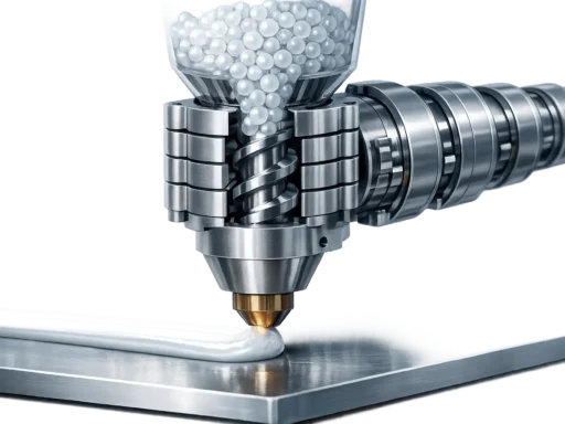
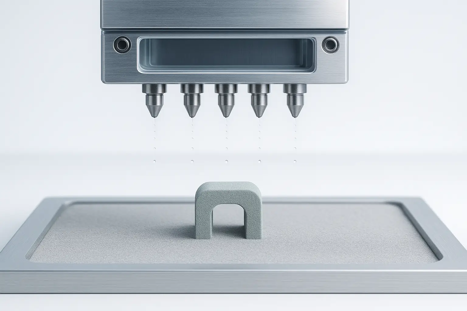
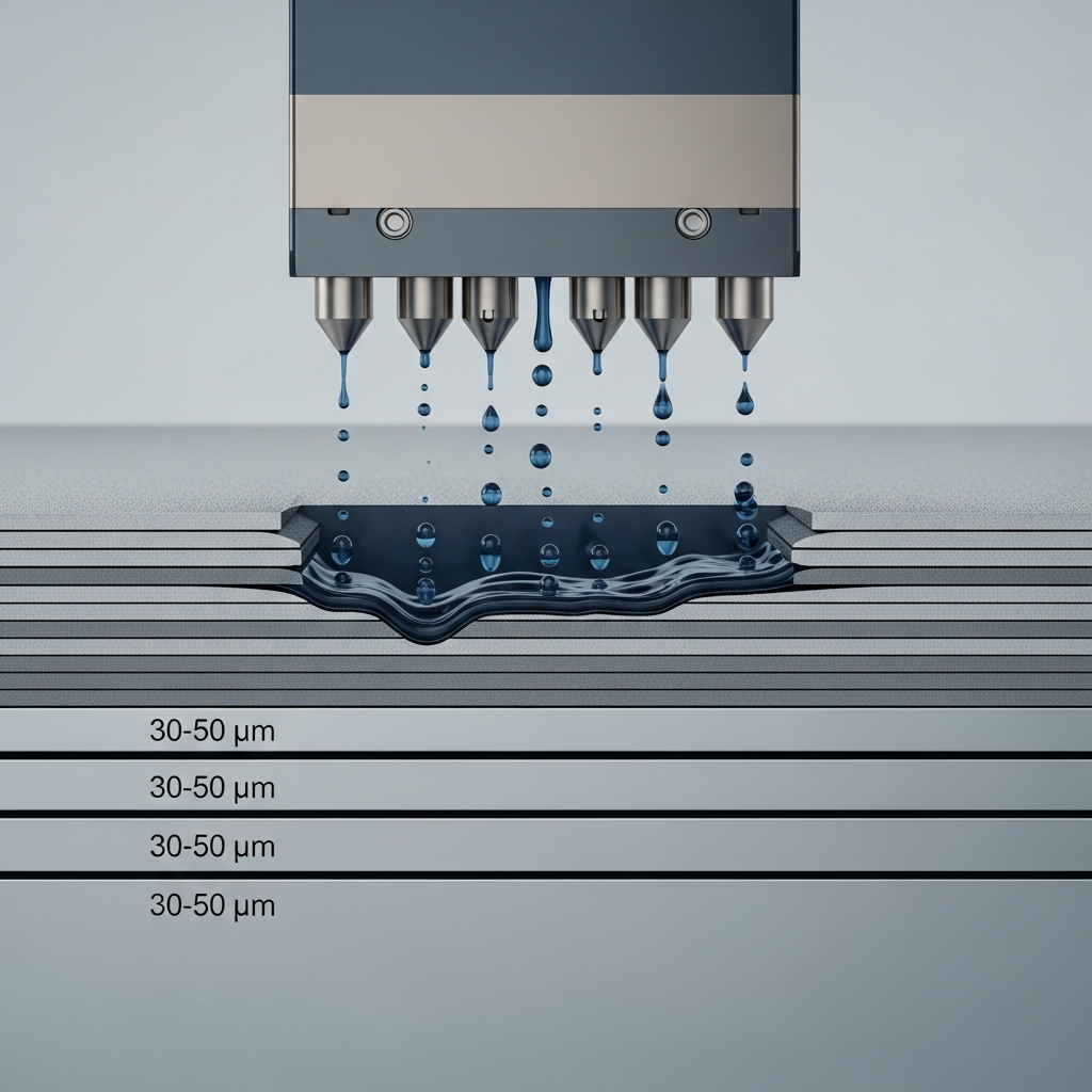
At its core, binder jetting operates by spreading fine metal powder in a thin layer, then using an industrial inkjet printhead to deposit droplets of binder—typically a liquid adhesive—onto select regions. This bonding occurs at room temperature, eliminating thermal stresses, support structures, and allowing high throughput. [1]
The effectiveness of the binder jetting process depends on several technical factors:
- Powder particle size distribution—most metal binder jetting uses PSDs of 5–50 µm, with optimum flow achieved using 10–50 µm particles.
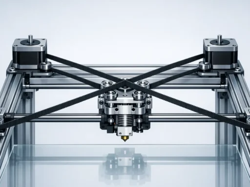
- Powders need to be spread consistently; research indicates that oscillating the recoating blade above 200 Hz achieves a packing fraction of 50–60%—crucial for part density and quality.
- Control of binder droplet behavior is critically important. Inconsistent spread or insufficient penetration can create a “depletion zone” below the print surface, measured around 56 ± 12 µm for stainless steel 316 powders. Sintering increases the risk of deformation, with shrinkage and porosity requiring compensation. Machine learning methods now help predict and reduce dimensional deviations in complex green parts. [9] [11] [12] [13]
Types and Performance
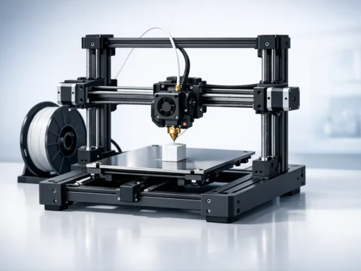
Binder jetting equipment for metals ranges from desktop research models to large-scale production machines. High-throughput systems focus on rapid manufacturing of multiple components, while high-precision machines are optimized for fine resolution, accuracy, and detail.
In the industrial space, the Desktop Metal X160PRO offers a build volume of 800 × 500 × 400 mm (160 L), build speeds up to 3 120 cc/hr, and layer resolution as fine as 30 µm. The Production System P‑50 boasts up to 12 000 cc/hr throughput and a sizable 5 meter machine length, making it one of the fastest in class. Markforged’s PX100 prioritizes accuracy with a 35 µm Z-layer and static precision better than 1 µm, alongside 1 600 dpi printhead resolution. These systems address different user needs, which is best illustrated by a comparison table. [6] [7] [8]
| Model | Build Volume (mm) | Build Speed (cc/hr) | Z-Layer (µm) | Accuracy | System Weight (kg) |
|---|---|---|---|---|---|
| Desktop Metal X160PRO | 800 × 500 × 400 | 3 120 | >30 | >1 µm voxels | 3 700 |
| DM Production System P‑50 | n/a (large) | 12 000 | n/a | n/a | 5 400 |
| Markforged PX100 | n/a | 1 000 | 35 | <1 µm static | n/a |
Binder jetting process systems deliver competitive build accuracy—static accuracy has reached better than 1 µm in specialized machines, with layer heights between 35–50 µm for metal parts. After sintering, green parts experience shrinkage: typically 0.8–2% for infiltrated small components, about 3% for larger parts, and as much as 20% for parts undergoing full sintering. Finished densities reach 97% after sintering but drop to about 90% for infiltrated parts due to residual porosity. Surface roughness can be improved post-process from Ra ≈ 6 µm (as-printed) to 3 µm with bead-blasting; comparatively, laser-based powder systems (DMLS/SLM) produce Ra around 12–16 µm. These factors influence functional applications and dictate the required amount of post‑processing for critical surfaces. [1] [2] [3] [4] [5] [6] [7] [8]
Applications
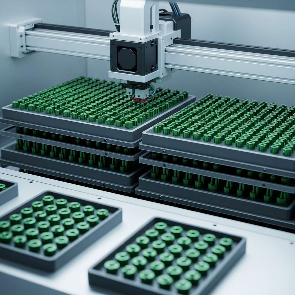
Metal binder jetting sees broad adoption in the automotive, aerospace, medical, and tooling industries. Because it requires no support structures and allows for large build volumes, it is particularly valuable for mass production of small metal parts, complex prototypes, and custom insert components. The ability to rapidly manufacture molds and tooling without heat distortion gives manufacturers a significant cost benefit. [2]
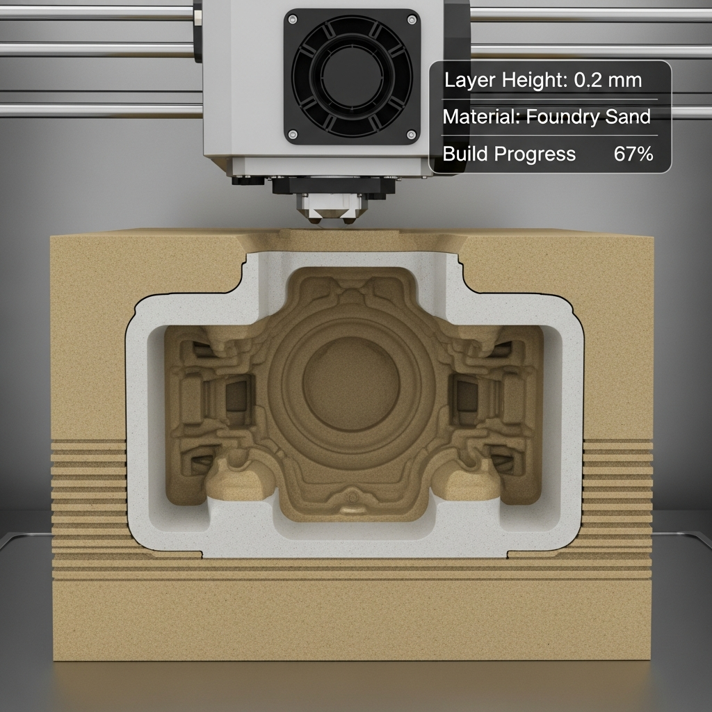
Functional applications include end-use metal parts, investment casting patterns, and sand casting molds. Sand molds produced with binder jetting have enabled casting of single blocks weighing hundreds of kilograms—far beyond the capability of most direct metal powder-bed technologies. The large build envelopes (such as 800 × 500 × 400 mm) and high deposition rates (up to 12 000 cc/hour in the Desktop Metal P‑50) permit production of hundreds to thousands of metal components in a single build cycle, reducing unit cost for high-volume runs. Compared to selective laser melting or direct metal laser sintering, binder jetting systems offer both geometric freedom and economies of scale, provided that density and infiltration requirements—characteristic of powder-based 3D printing—are acceptable for the part’s performance criteria. [2] [5] [7] [10]
Research and Developments
Recent research efforts in metal binder jetting focus on maximizing accuracy and density while minimizing deformation during sintering. Sintering deformation can range from 25–50% depending on the initial porosity of the printed “green” part, but advanced machine learning has demonstrated mean positional deviations as low as 0.7 µm on large, 63 mm parts. Improvements in powder spreading—such as the adoption of >200 Hz transverse oscillation—enable more consistent layering and raise the compacted powder’s packing density to 50–60%. These advancements are rapidly moving the technology toward higher reliability and broader adoption in high-precision manufacturing environments. [12] [13]
FAQ
1. What is the binder jetting process and how does it produce metal parts?
The binder jetting process selectively deposits a liquid binder onto a bed of fine metal powder, joining particles layer by layer at room temperature. After printing, the green part is cured and then sintered or infiltrated to achieve final mechanical properties. [1]
2. How fine is the powder-based 3D printing in terms of resolution and layer thickness?
Metal binder jetting achieves typical layer thicknesses of 35–50 µm, with powder particle sizes ranging from 5–50 µm and advanced systems offering >1 600 dpi printhead resolution for high detail. [1] [8] [9]
3. What accuracy and shrinkage values are typical in metal binder jetting?
State-of-the-art metal binder jetting delivers static accuracy better than 1 µm, while green parts shrink by around 0.8–2% (infiltrated), 3% (large parts), and up to 20% during full sintering, requiring precise compensation in the build strategy. [5] [8]
4. How fast is metal binder jetting compared to other powder-based 3D technologies?
Top machines like the Desktop Metal P‑50 offer up to 12 000 cc/hr build speeds—significantly outpacing most powder-bed fusion systems—making binder jetting one of the fastest metal AM options for high-volume production. [7]
5. What are the main limitations regarding porosity and post-processing in metal binder jetting?
Sintered metal parts achieve densities up to 97%, but infiltration methods yield about 90% due to residual pores. As-printed surface roughness is Ra 6 µm (down to 3 µm after bead-blasting), often requiring additional finishing for demanding applications. [3] [4]
6. How are current research developments improving metal binder jetting performance?
Machine learning dramatically reduces dimensional errors during sintering, achieving deviations as low as 0.7 µm, while enhanced powder spreading methods boost part density to 50–60%. These innovations are improving reliability and final part quality. [12] [13]
Sources
- Hubs: What is Binder Jetting 3D printing?
- Amazemet: Binder Jetting Technology
- Powder bed and inkjet head 3D printing – Surface finish, porosity
- Hubs: Binder Jetting density and infiltration
- Hubs: Binder Jetting – Shrinkage and Accuracy
- VoxelMatters: Guide to Binder-Based Metal 3D Printing
- VoxelMatters: Desktop Metal System Specs
- VoxelMatters: Markforged PX100 Specifications
- Amazemet: Powder Particle Size in Binder Jetting
- it.wikipedia.org: Binder Jetting History and Standards
- Wikipedia: Porosity Depletion Zone Study
- arXiv: Machine Learning Correction of Sintering Deformation
- arXiv: Transverse Oscillation for Powder Spreading