Summary
In 3D printing, overhang refers to regions of a part that extend outward, lacking direct vertical support from layers below. The widely cited “45° rule” states that any overhang angled greater than 45° from vertical typically requires support structures. Different printing technologies and materials yield variations in overhang tolerance, so understanding these values is critical for optimizing prints and minimizing unnecessary supports. [1][2]
Historical background
Consideration of overhangs in 3D printing was first widely discussed with the rise of fused deposition modeling (FDM) systems, especially following the RepRap project’s public emergence in the mid-2000s. The challenge of minimizing support structures while achieving geometrically complex prints led to the popularization of the 45° guideline for overhangs, a rule still referenced today in multiple manufacturers’ and academic sources. This early focus was driven by practical needs: printing reliable parts with fewer supports improves ease of post-processing and resource efficiency. No reliable figure found for the specific inventor or year of introduction.
Principles of overhang in 3D printing
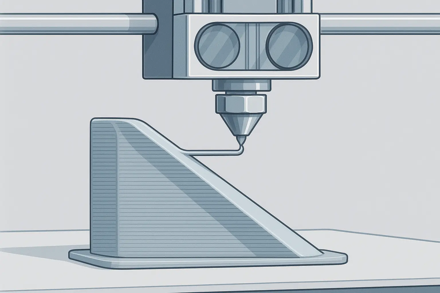
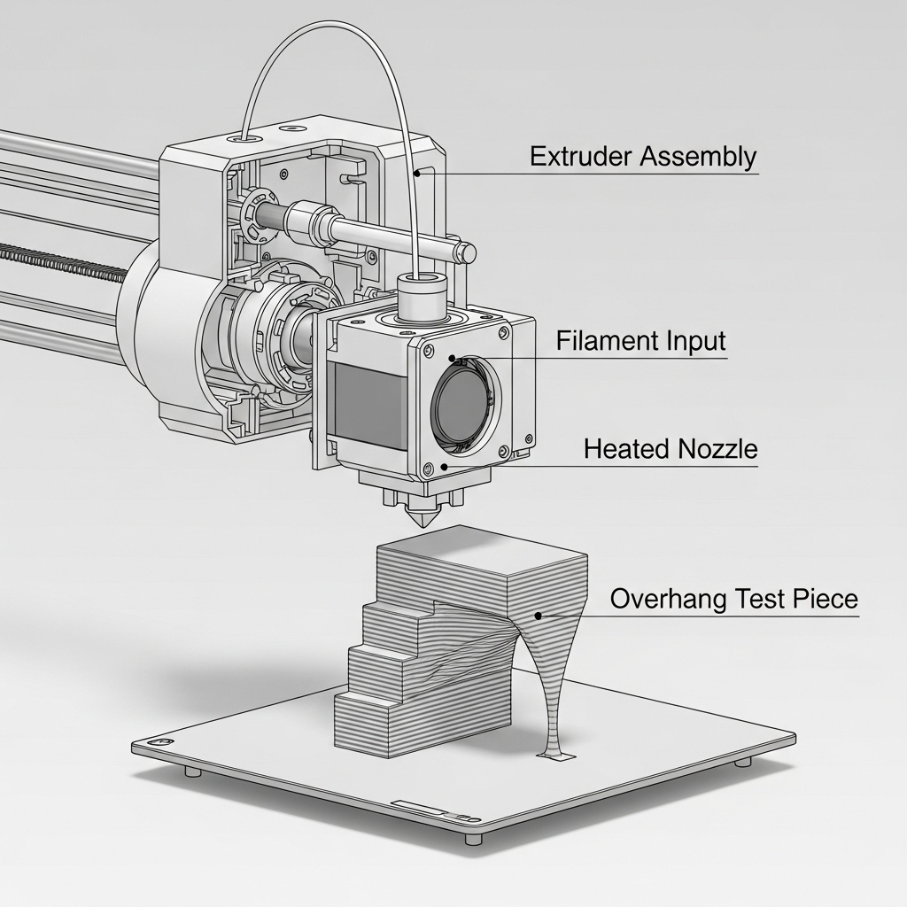
An overhang in 3D printing is any geometry or section that is not directly supported by material beneath it — this can be a flat, horizontal feature or an angled extension. Such features challenge the printer’s layer-by-layer process, which relies on each new layer adhering to material below.
Thresholds for 3D printing overhangs are regularly cited: sloping overhangs from vertical up to 45° can generally be printed successfully, but beyond 45°, as the angle approaches horizontal, supports become increasingly necessary. Some guidelines state that overhangs at 45° to 60° may succeed unsupported; when the angle exceeds 60°, use of supports is nearly always required. A few sources describe a minimum “self-supporting” angle of 30°, with anything less likely to fail without support. [1][2][3]
Types and material variation
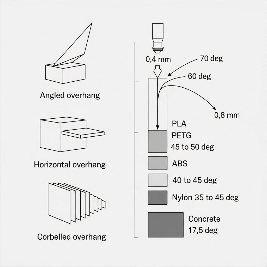
Overhangs can be grouped into:
- Angled overhangs (sloping features extending outward)
- Horizontal overhangs (flat features, nearly or completely parallel to the build plate)
- Corbelled overhangs (unique to concrete printing, created by incremental offset)
Classification is essential, as both material and design influence achievable angles. For example, the maximum overhang angle for PLA without supports is 55–60° (excellent), while PETG is rated at 45–50° (good), ABS at 40–45° (poor), and Nylon at 35–45° (poor). Nozzle size also factors in: the Ultimaker S3 achieves a 60° overhang with a standard 0.4 mm nozzle, but up to 70° with a 0.8 mm nozzle. In 3D concrete printing, the corbelling process produces overhangs with a maximum slope angle of just 17.5° from vertical, far lower than plastic-based FDM. [4][5][6][7][8]
Performance metrics
Material‑specific overhang tolerance
The defining metric for 3D printing overhangs is their maximum unsupported angle before sagging or failure, which varies by filament type and printer setup. For example, PLA’s tolerance is highest — up to 60° without support — making it suitable for intricate models. PETG handles overhangs between 45° and 50°, while ABS and Nylon lag with 40–45° and 35–45°, respectively. Unique to concrete printing is the “corbelled” approach, limited to just 17.5° due to the material’s structural properties. Horizontal overhangs, nearly parallel to the build plate, typically require support if wider than 2–5 mm. Crucially, nozzle diameter controls filament laydown: a wider 0.8 mm nozzle maintains filament shape over an angle up to 70°, compared with 60° for a standard 0.4 mm nozzle using PLA, as verified in independent printer tests. The table summarizes these differences for rapid reference. [5][6][8][7]
| Material/Technology | Max Overhang Angle (°) | Nozzle (mm) | Max Angle (°) | Special Cases |
|---|---|---|---|---|
| PLA (FDM) | 55–60 | 0.4 | 60 | |
| PLA (FDM) | 55–60 | 0.8 | 70 | |
| PETG (FDM) | 45–50 | 0.4/0.8 | — | |
| ABS (FDM) | 40–45 | 0.4/0.8 | — | |
| Nylon (FDM) | 35–45 | 0.4/0.8 | — | |
| Concrete (Corbelling) | 17.5 | n/a | 17.5 | Corbelling method |
| Any (Horizontal Overhang) | 90 (unsupported span) | n/a | 2–5mm | Spans above 2 mm demand support |
Applications
Understanding 3D printing overhangs is crucial for several advanced tasks: orienting models for best results, planning and generating support structures, and configuring topology optimization tools that automate design-for-manufacture within printers’ physical limits. [1][9]
Research updates
Recent research in topology optimization now allows design tools to mathematically constrain overhang angles. An ArXiv study describes applying a maximum permitted overhang via calculating the angle gradient of the model’s surface, comparing it to a preset critical slope. This digital approach ensures automatically generated structures respect printer-specific limits, streamlining manufacturability. [9]
Level-set methods, detailed in a separate ArXiv publication, have also been applied to overhang optimization by evolving the geometry so that surfaces never exceed the critical angle, producing parts that require fewer supports. Meanwhile, new slicer tools such as Curvy can tune the density and geometry of support structures based on local overhang angles, allowing optimized print times and material consumption. Together, these research advances mark a significant step forward in automating the complex balance between creative freedom and technological restraint in additive manufacturing. [10]
Q&A (FAQ)
-
What is the maximum overhang angle for 3D printing without support?
The typical guideline is 45° from vertical, meaning overhangs steeper than 45° generally require support structures. Some prints may manage 45–60° without support in favorable conditions. [1][2] -
How does overhang angle tolerance vary by material?
For PLA, the maximum is 55–60°; PETG achieves 45–50°; ABS is rated 40–45°; and Nylon manages 35–45°, each under optimal settings. [5] -
Why does nozzle size affect overhang capability?
A larger nozzle, such as 0.8 mm versus 0.4 mm, places down a wider bead of melted filament, improving the ability to print at steeper angles. For example, an Ultimaker S3 can achieve a 70° overhang with PLA using a 0.8 mm nozzle compared to 60° with a 0.4 mm. [8] -
At what angle are supports mandatory for angled overhangs?
Overhangs with angles below 30° will generally fail without support; thus, support placement is mandatory for slopes under this value. [3] -
In concrete printing, what is the maximum slope without support?
With corbelling, the maximum unsupported slope documented is just 17.5° from vertical, reflecting the limits of cementitious material stacking. [7] -
How do topology optimization methods constrain overhang?
Topology optimization tools generally apply a gradient-based constraint, limiting local surface angles to remain below a user-defined “critical” overhang value. This automates overhang management during computer-aided design. [9]
Sources
- Polar Cloud: Tip: Design – No Overhang
- University of Melbourne – 3D Printing Design Guidelines
- Nexa3D – Design Guide
- JLC3DP – How to Get Better Overhangs in 3D Printing
- CMAC – Improving 3D Print Overhangs and Bridges
- Nexa3D – Design Guide (horizontal overhang detail)
- MDPI – Appl. Sci. Article on 3D Concrete Printing Corbelling Angles
- Ultimaker Cura Community – Support Overhang Angle
- ArXiv – Topology Optimization for Maximum Overhang
- ArXiv – Level Set Methods for Overhang Optimization